Recently, questions have been increasing as to why an arc is suddenly drawn when the DC plug is disconnected from the inverter when the inverter is switched off. Since this has already happened to me and we found the reason for it quite quickly, I would like to report about it here in the blog.
During repeat tests on photovoltaic systems or in the event of troubleshooting, all strings are often separated from the inverters in order to then measure them individually. Usually with a device that measures the open-circuit voltage, the short-circuit current and the insulation resistance of the respective module string in one measuring process. If you do it correctly, before disconnecting the DC lines, each module string is checked with a current clamp to see whether a direct current is still flowing. Only when this test ensures that the cables are de-energized can the DC plugs be separated from the inverters. But, hand on heart, who does this so carefully every time?
Often in the heat of the moment the DC plug is quickly pulled out and in some cases a huge arc is drawn. As a rule, this is not only associated with a lot of fright, it can also be dangerous. For example, if you are standing on a ladder with an inverter that is difficult to access. Not to mention the impact on the quality of the DC plug contacts. To be on the safe side, these should be replaced after a major arcing event, as it can no longer be guaranteed that the connection will still have the same low resistance as it did before. With built-in plugs in the inverters, this is of course associated with a larger action. In the worst case scenario, the inverter must be sent for repairs. Of course, no one does that and in practice it is precisely because of such events that plug connectors on the inverters become hot and at some point can no longer be opened at all.
Long story short: Please always measure the DC currents and make sure that none are flowing before you pull the plugs.
But now to the actual question, why does current still flow when the DC switch on the inverter is switched off?

The answer is very simple: several strings were connected in parallel on the inverter and the DC switch on the inverter does not separate this parallel connection. The parallel connection of the strings is therefore in front of the switch. This problem also occurs when many strings are connected in parallel in a DC connection box. However, there are usually string fuses in DC junction boxes, which usually trip. But now to the question of where the flow of electricity actually comes from?
These are compensating currents between the module strings, which arise because two strings have a different voltage. There are numerous reasons for different voltages, which we will now go through one by one.
- One of the two strings has partial shading. In this case, the voltage difference is rather small (see dependence of the voltage on the irradiation = logarithmic function) and a correspondingly small current flows.
- A different number of modules was installed in the two parallel-connected strings. Depending on how much the string lengths differ, significant compensating currents can flow here.
- In one of the two module strings there are modules with defective, short-circuited bypass diodes or open cell connectors, so that a third of the voltage of one or more modules is missing.
- One of the two module strings was connected with the wrong polarity. That’s the worst case. Here the two module strings are not connected in parallel, but in series. The driving voltage is then no longer the voltage difference between the two strings, but rather the sum of the two open-circuit voltages of the individual strings.
What can you do if the current is not equal to 0A?
First of all, it should be noted that the currents in larger PV systems are rarely exactly 0A. Due to slightly different irradiations on both strings, a small current of 100-200mA often flows. This indicates that the voltage difference is not too large and the plugs can be safely disconnected. However, if the current is already in the range of 1A, caution is advised and an arc can occur when the plug is pulled out. As an example, currents of around 1.5-2 A are completely normal with just one module less in one of the two strings.
If a current of this magnitude flows, you must leave the DC plugs plugged in. Only when the radiation is lower and the current is only 100-200mA can the plug be safely pulled out. The next step is troubleshooting. You have to find out where the two parallel-connected module strings are in the field and then make sure that both strings deliver the same voltage.
Incidentally, such errors often occur with new systems. It quickly happened that a module that actually belonged to string 1 suddenly ended up in string 2. In this case, string 1 has one module too few and string 2 has one too many, with the result that the voltage difference between the two strings already corresponds to the voltage of 2 modules.
In old systems, larger compensating currents are always associated with errors in one of the two lines. This could be, for example, short-circuited bypass diodes in one of the two strings. However, it also often happens that service teams remove modules with broken glass from the line and, if the replacement is not yet on site, simply bridge the missing module.
Is there a way to determine the amount of compensating current?
Finally, I would like to reveal a trick on how you can easily determine how large the balancing currents flowing in each case are. All you need is the iv-curves of the two individual strings.
The following picture shows schematically the parallel connection of two strings.
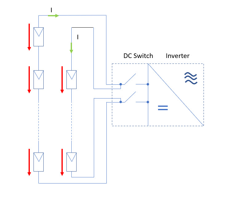
If you do a voltage circuit (keyword: Kirchhoff’s mesh rule), it immediately becomes clear that the same voltage must be present at the terminals of both solar modules. This is, so to speak, impressed by parallel connection. If there is a balancing current, this current flows either from string 1 to string 2 or from string 2 to string 1. In any case it is (hopefully) clear that the currents in string 1 and string 2 must be the same because the DC switch to the inverter is switched off. When a current flows, it can only flow between the two strings. There is no other option. If I now have 2 module strings whose voltages are exactly the same and whose currents are the same but with a different sign, I can determine the operating point by entering both iv-curve-characteristics into a single current-voltage diagram. If the term operating point means nothing to you. The operating point is the crossingpoint of the two curves that occurs after the parallel connection. So the current and voltage that can be measured when both strings are connected in parallel. The image below shows how you can easily determine this operating point graphically.

If you are now wondering why one of the two characteristic iv-curves on the voltage axis (X-axis) was mirrored, please refer to the first picture (above). If a compensating current flows, it must always have the opposite sign in one of the two strings as in the other string. I1 = -I2. This can be achieved graphically by simply mirroring the characteristic iv-curve of the string whose current becomes negative (the one with the lower voltage) on the voltage axis (X-axis). The intersection of both characteristics is then the operating point.
You can see directly from the representation of both iv-curve characteristics that this current can become quite large even with small voltage differences. If one assumes that the open-circuitvoltage in modern modules is approx. 20% above the MPP voltage, then in a string with 20 modules a difference of just 2 modules results in a balancing current in the order of magnitude of the nominal current (Impp) of the modules. The better the modules are and the higher the fill factor of their iv-curve-characteristic, the greater the resulting compensating current.
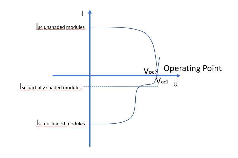
If you look at the resulting compensation current for comparison when one of the two parallel strings is shaded, you can see that this current is significantly lower.
When troubleshooting, the following should be noted:
If you want to measure the individual strings in a system and for this purpose you want to separate the DC connectors from the inverters, always switch off the inverter first and then measure the currents.
If a larger current flows, this already indicates a fault in the string in which the current is negative. In order to recognize this, it is necessary to note the sign of the compensating current. Note: DC current clamps always have a small arrow that indicates in which direction the positive current direction is measured.
The string must then be found in the field to eliminate the error. This can be done with the thermography method, with the pvTector or with electroluminescence. Or of course with a correct strand plan. Then the error must be found in this strand. Thermography is the best method here during the day.
If you would like to deal more intensively with the topic of troubleshooting photovoltaic systems, please refer to our regular seminars on this topic. You can find the current dates here on our website.