If you read this blog regularly, you have already noticed: The solar industry is currently struggling with a major serial defect involving backsheet failure. For every operator of a photovoltaic system, this immediately raises the following question: Which backsheets have been installed for my own system? This question can now be answered, and how this came about is described in this article of mine. (General note: Many of the links in this document lead to German-language pages. I apologize for that.)
First, a few brief introductory remarks on the subject of backsheeting: In the basic structure of a commercial solar module with crystalline solar cells, a layer comprising EVA foil is located immediately behind the front glass pane, and subsequently followed by the solar cell itself. The rear of the cell is covered by another EVA layer which is followed by the backsheet, which can also consist of several layers. I am talking about glass-foil modules here. In glass-glass modules, the rear EVA layer is directly followed by a second glass pane. The solar cells are thus embedded in a sandwich of plastic foils laminated together in an oven during production. The EVA is essentially used to embed the solar cells and ensure that the different coefficients of expansion of glass and silicon do not lead to mechanical stresses. The most important property required of the EVA is to retain its transparency despite permanent exposure to UV radiation, and to allow the greatest possible amount of sunlight to pass through to the solar cells. It should be pointed out here once again that plastics often tend to change their properties under continuous exposure to short-wave (and thus high-energy) UV radiation. The backsheet on a solar module is primarily meant to protect the solar cells from ambient influences. If possible, no water vapour should diffuse into the laminate, as moisture can corrode the contacts between the individual cells. Furthermore the backsheet foils must ensure high electrical insulation for the embedded cells. After all, modern PV systems employ voltages reaching 1500V. Considering that inverters without transformers are used almost exclusively today, touching a damaged backsheet during operation can quickly become life-threatening. It is therefore absolutely necessary for the backsheets to permanently maintain their insulation capacity. To monitor this condition during a PV system’s long service life, the inverters perform an insulation test every morning before being connected to the grid. For this purpose, test voltages of 1000V or 1500V are usually applied between the short-circuited solar generator and earth. The amperage then measured is used to determine the insulation resistance with the help of Ohm’s law. Anyone interested in the details of these measurements can refer to this blog article (in German). According to the internationally valid standard DIN EN62446-1, a module string’s insulation must never drop below 1MOhm.
For some time now, we have observed a serial defect involving backsheet failure in solar modules. This defect increases the downtimes of the affected PV systems, as the inverters do not connect the system to the grid in the morning if the insulation values are too low. In the final stage of the defect, the backsheets often fail completely and lead to destruction of the modules. This problem has already been pointed in this blog by the two articles linked below:
Article 1: “The PV industry needs to deal professionally with problems”
Article 2: “Systematic localization of faulty insulation in PV systems (German)”
Before describing how to identify the type of foil used by a solar module, I would like to display three instances of the observed problem again using 3 typical photos below.
Defect type 1
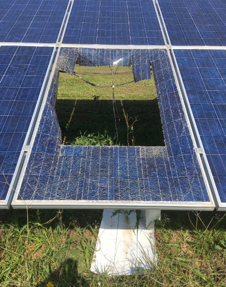
In the first case, cracks in the embedding foil appear, always in the spaces between the cells. As a result, the cell connectors become so badly damaged that extreme heat is inevitably generated, in turn destroying the module’s glass panes. Entire rows of cells consequently drop out of the modules, as displayed in the images. This phenomenon was first observed in southern Europe.
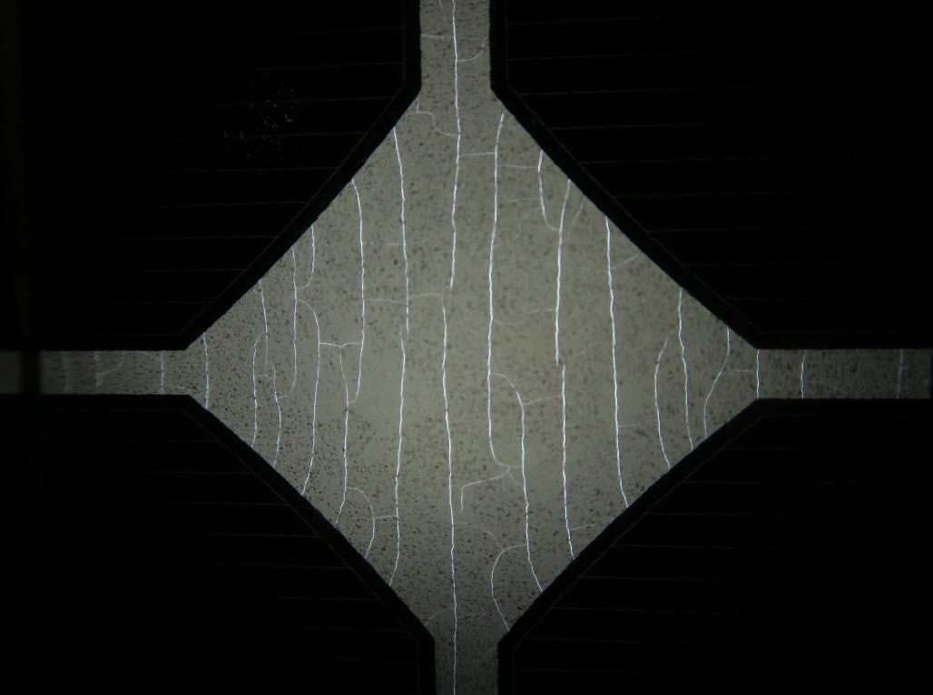
Defect type 2
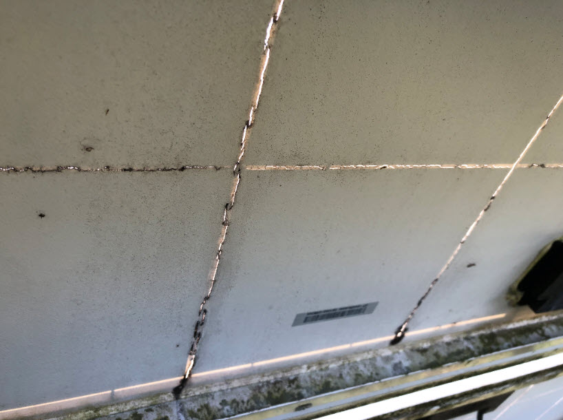
In the second case, only the inner layer is affected by the foil sandwich at the rear. Unfortunately, this problem is not apparent at first glance. However, shining a flashlight through the intercellular spaces clearly reveals tiny cracks in the backsheet.
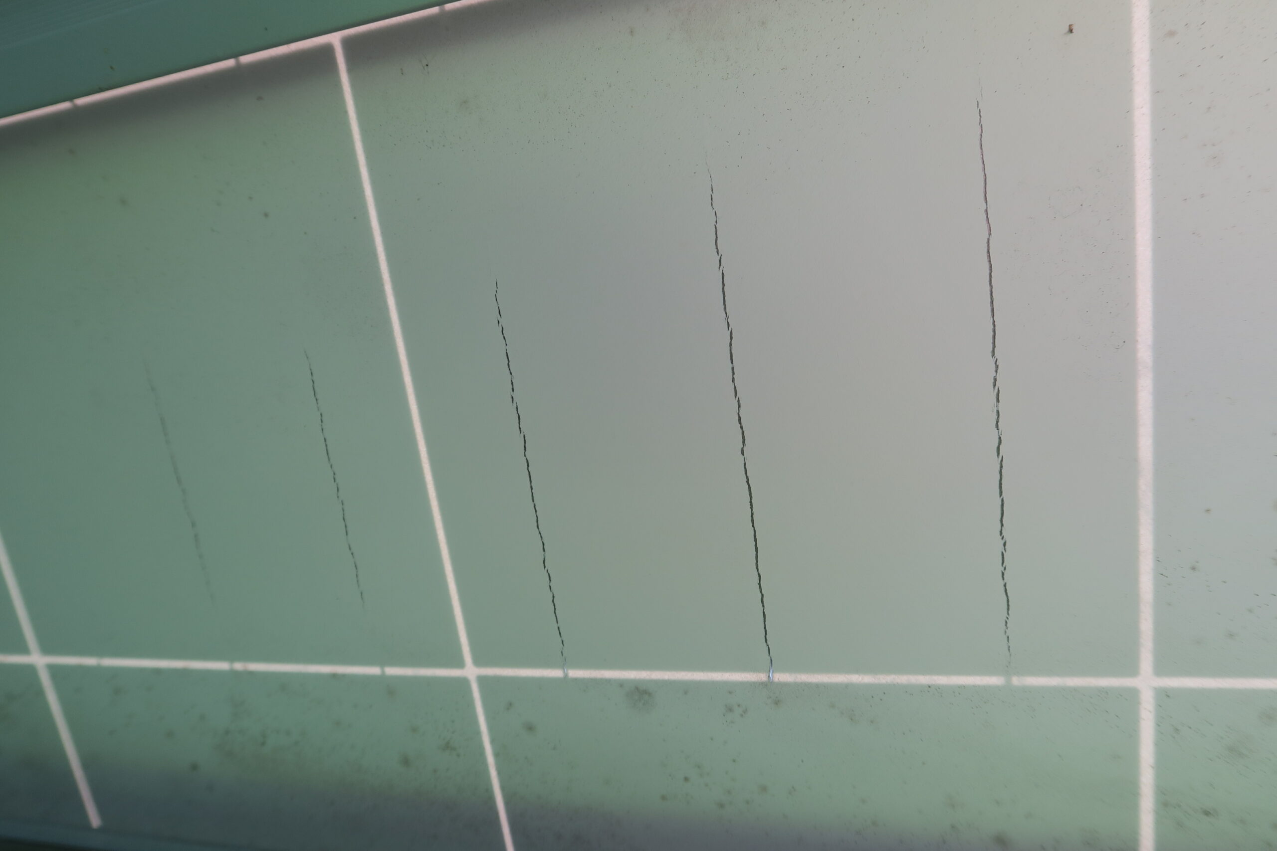
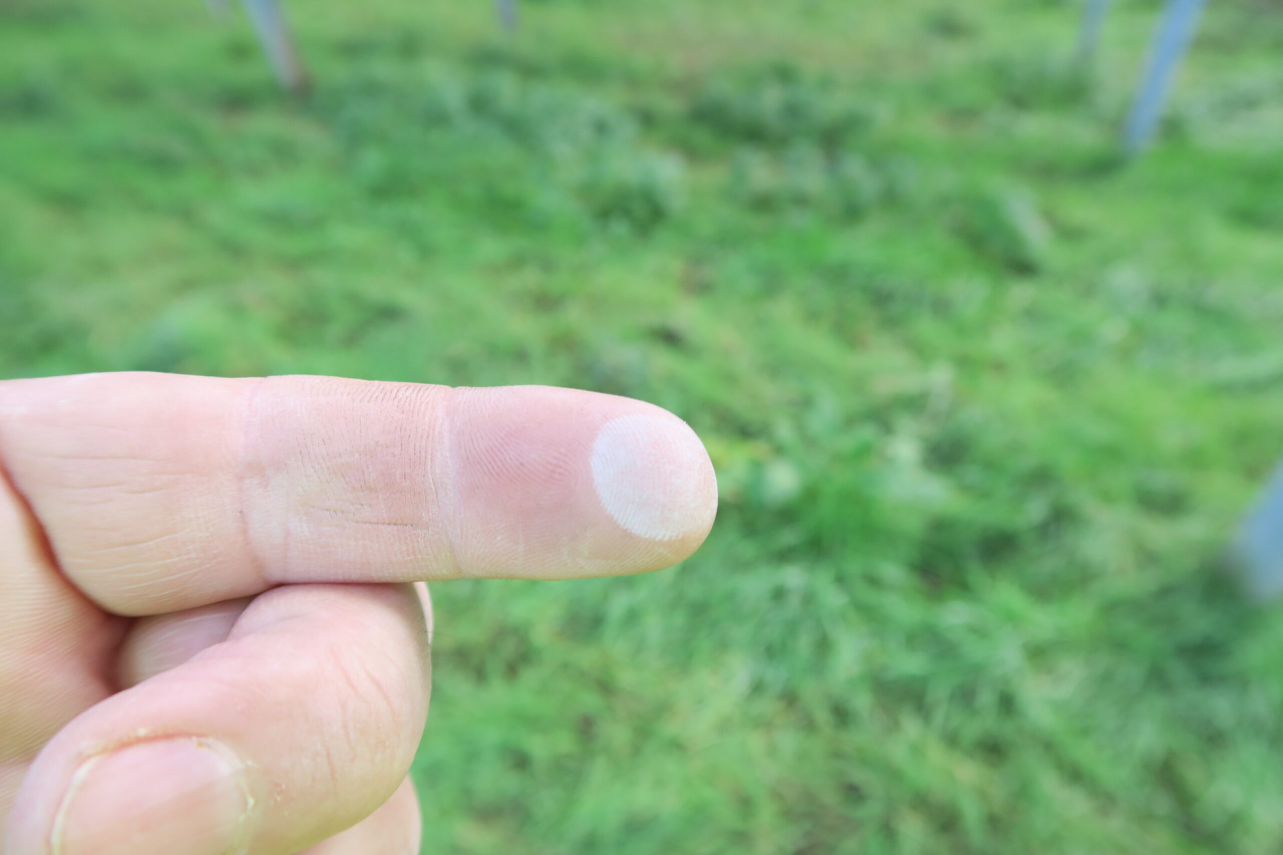
Defect type 3
In the third case, cracks in the foil can be seen above the rear cell contacts. The systems we examined also exhibited chalking in all such cases.
Is it possible to identify the type of foil?
The operator of a system affected by the problem described above asked us whether it would be possible to identify the types of foil causing this problem to allow early reaction. The background to this was another PV system of the same operator, where this problem had not yet revealed itself. There was therefore a desire to clarify whether foil failure would also have to be expected in the second park.
Because I had never dealt with embedding foils before, this was new territory for me and I first had to obtain an overview of the examination methods possible here. Research showed that the ZSW laboratory in Stuttgart is able to identify the backsheets of solar modules. For this purpose, modules need to be dismantled and brought to the laboratory. The tests are destructive. As part of the examination, parts are cut out of the module for the purpose of subsequent analysis using the FTIR method. FTIR stands for Fourier-transform infrared spectroscopy. More information on this process is provided here. More information on this process is provided here. In simple terms, spectroscopy methods use the interaction of near-infrared radiation with the molecules of embedding foils in order to identify these. Each molecule absorbs one or more wavelengths of radiation, so irradiating the material creates a typical “fingerprint” which, in turn, allows conclusions to be drawn about the material’s composition. In the case of foils with several layers, however, each layer must be exposed separately and examined individually to permit identification. This can be done in the laboratory.
In our practical case, we were able to determine that the material of the foils from the second park had a composition different to that of the defective foils, and was not expected to crack to the same extent.
Is a laboratory visit always necessary?
Recalling a low-cost IR spectroscopy method which had come to my notice a few years ago, I decided to do some further research on portable solutions which might be usable in solar parks without a need to remove modules. After all, our primary concern in the solar industry is not so much highly accurate identification of foil materials, but rather detection of defective foils and the ability to distinguish these from perfect foils. A mobile, non-destructive analysis method here would allow development of a database in the course of time.
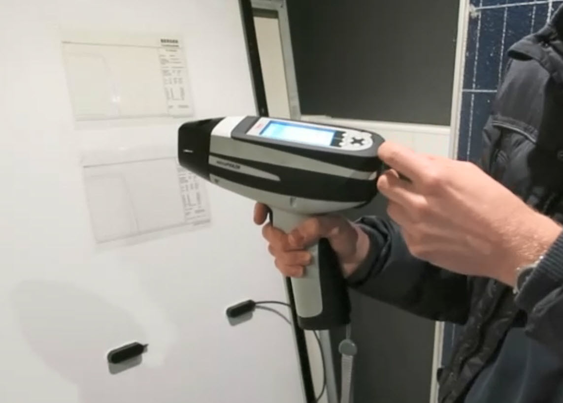
Inspired by this idea, we ultimately contacted Analyticon, a company which sells mobile infrared spectroscopy devices. An employee visited us and an attempt was made to determine whether it is possible to distinguish between the spectra obtained from the embedding films on the numerous solar modules accumulated as test objects by then in our laboratory. Here is an example of a device used for this.
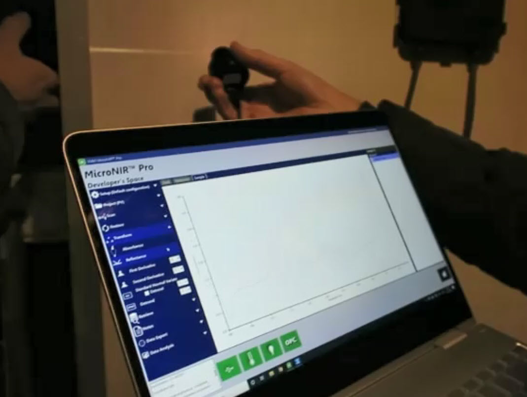
We discovered that the spectra can be distinguished, but that additional know-how is required to interpret the results to be able to assign the respective spectra to a specific embedding material. The relevant devices cost more than € 20,000 each. It would therefore take not only time but also the necessary money to pursue this approach.
Second attempt
A few weeks later, we were visited by two young men from another company which we had also become aware of through an Internet search. It was the company Trinamix from Ludwigshafen, a start-up spin-off of BASF based there. In contrast to the first lab session, the two gentlemen here had brought only a small device with which they took just a few tests of the solar modules. For this purpose, the small hand-held device was simply placed against a module’s rear, and a button was pressed. Shortly afterwards, a measurement result appeared on a mobile app. These gentlemen were concerned mainly with the details of the desired technology’s application, the estimated size of the market for it, and the information typically required about the condition and consistency of solar modules’ backsheets. I then provided the gentlemen with plenty of information about photovoltaic systems and, in particular, the current problem with the backsheets. The two left again, saying they would consider whether the topic would be of interest to them … that was the end of the matter for the time being.
A new tool for examining solar modules emerges
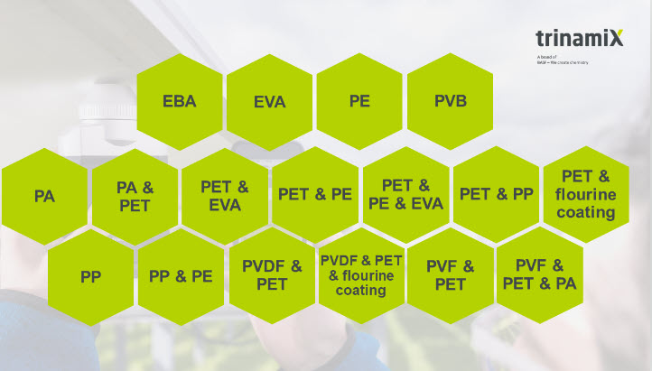
Suddenly and completely unexpectedly, about half a year later, our phone rang and an employee of the aforementioned company was on the line. I was proudly notified that a device was now ready, the corresponding app had been developed, and they wanted to introduce me to the device in our office. Frankly, I was quite surprised that the topic had been handled without any further communication and looked forward to the next visit by Trinamix. I was very impressed by the new solution introduced to me at the next meeting. By then, they had teamed up with the Austrian Research Institute for Chemistry and Technology (OFI) and the Polymer Competence Center Leoben GmbH (PCCL), and jointly created a database of backsheets typically used in the PV industry. The small portable device functions according to the principle of transflection. The device emits radiation in the range between 1400 nm and 2400 nm, i.e. in the invisible infrared range, through a solar module’s backsheet. The radiation is then reflected by the solar cells and received again by the device. The reflected radiation is spectrally resolved and compared to the original radiation to determine which wavelengths of the spectrum were absorbed by the backsheet material. As mentioned further above, these wavelengths are material-specific and provide a unique “fingerprint” of the employed material. The data are then transmitted from the device to an Internet database and compared there with known material samples. Via this type of assignment, known materials can then be clearly identified and displayed in a smartphone app immediately after the measurement. Without time-consuming laboratory tests, one thus obtains a direct indication of the material used in the backsheet foil under investigation. The measurement technique also determines, as a small additional detail, the embedding material, which is usually EVA as mentioned previously. The materials and their combinations shown below can already be recognized.
Practical test
We have now integrated the device into our toolbox for investigating PV systems, and have already carried out initial practical tests with it. In terms of handling, the device is easy to operate. Each module is measured in two stages: First the front and then the back. The measurement result is then displayed directly. If desired before the measurement, you can specify the module type and other details which are later transmitted automatically to the database together the measurement results. For subsequent evaluations in the office, the measurement data can be further processed on a PC; if necessary, spectra can be transferred in the form of an Excel file. Those familiar with the foils’ chemistry can certainly obtain further valuable findings from these raw data. I have now measured about 25 different module types with the device, and only in a few exceptional cases has it failed to deliver any results so far. These exceptions were two black solar modules and an ancient Kyocera mini-module. In the case of the black modules, I was told that the carbon black added to the foils for colouration is also opaque in the IR range, so that the spectroscopy method basically does not work here. The ancient module apparently still uses a type of foil which has not yet been registered in the database. Furthermore, only the type of embedding material (EVA) is indicated in the case of modern glass-glass modules. Because the database is constantly being expanded, one can assume that the system is able to recognize most common foil types. We have already been able to assign the foil type for two of the modules in our laboratory exhibiting the defect types depicted above: PA foil (PA stands for polyamide) and PET & fluorine coating. Whenever we visit a PV system in future, we will routinely record the type of backsheet in addition to all other data and store the results in a database. The solar industry appears to have received another useful tool for obtaining additional information about solar modules as an aid in fault diagnostics.

Update 15.11.2022: A first manufacturer reacts proactively to the problem and informs their customers.
Update 19.11.2022: A repair solution by DuPont (I have had no experience with this so far).