Exactly one year ago, I reported on a suspected serial defect related to open bypass diode paths on brand-new photovoltaic modules. At the time, the article still had a question mark, which can now be safely removed. I’ll attempt to summarize the latest findings on this topic in this article.
Serial defects in brand-new solar modules
This is a serial defect that occurs in brand-new solar modules with crystalline half-cells. These modules are now almost exclusively constructed using the so-called butterfly architecture. This module design consists of a total of six substrings, two of which are connected in parallel via a bypass diode. The different module sizes and module outputs differ primarily in the number of cell rows (there are 9, 10, 11, and 12 cell rows per substring) and in the cell sizes.
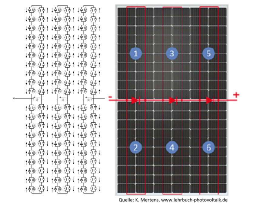
The module architecture, however, with three bypass diodes, each housed in a module socket, is the same for all variants.
Each module has a total of six solder tabs that run from the front of the module through the laminate to the rear and are soldered into the module bypassdiode/junctionbox. This automated process apparently repeatedly causes problems, both when bending the solder tabs and when subsequently soldering the connection tabs with a soldering iron.
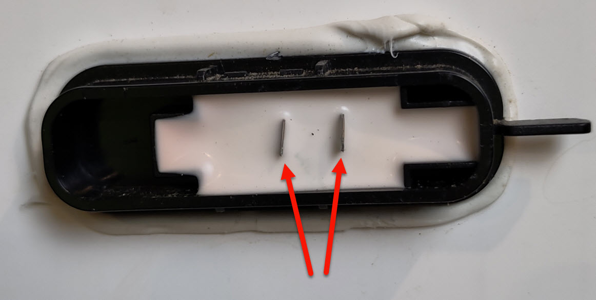
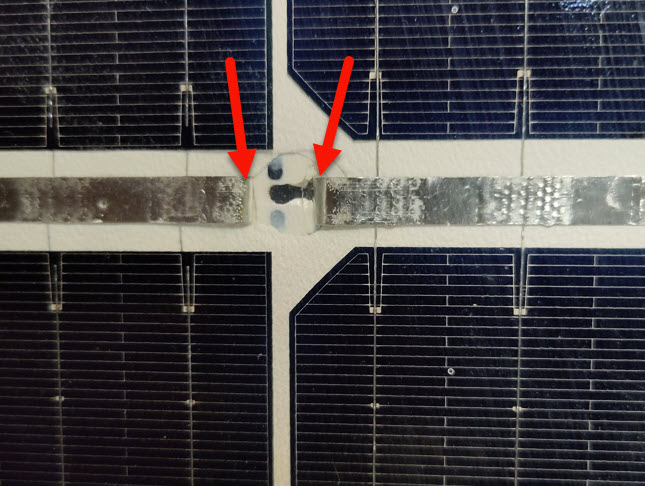
During one of our PV commissioning checks, we found a module with an open bypass diode, which the installer had kindly provided us with. After opening the junction box containing the bypass diode, I could see the solder tabs sticking out of the encapsulating compound. The solder tabs had clearly not been folded and soldered correctly. The more important finding from this example is that the module manufacturer clearly hasn’t implemented a testing process at the end of its production line to check these bypass diode paths for continuity. We’ve found cases of this type at six different module manufacturers so far, including two so-called “Bloomberg Tier 1 Manufacturers.” The fault doesn’t always become apparent immediately after opening the box. Sometimes you have to first scrape away the encapsulating compound to determine that the soldering wasn’t done correctly, resulting in a broken connection.

Problems were found at all six solder connections, and depending on which of the connections was not soldered correctly, the error manifests itself in different ways. While points 1 and 6 each lead to uncontacted, open substrings (these are always the outer substrings, on the left or right side of the module), errors at points 2-5 lead to open, uncontacted bypass diode paths.

The error with the open bypass diodes does not appear at first
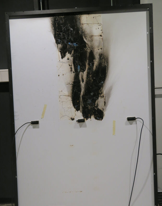
Since the bypass diodes are not working during normal, unshaded operation of a solar module, the problem is initially unnoticeable during normal operation. The bypass diode only becomes active when a shadow falls on the affected module or a cell is so dirty that the inverter decides to pull down the voltage during MPP tracking and activate the bypass diode. If the bypass diode is missing, it cannot be activated, and the current is forced through the solar cells in reverse bias. The voltage required for this can exceed 25V/cell in newer solar cells. Depending on the module current, this leads to significant power loss in the cell and, sooner or later, to the destruction of the backsheet and the module itself.

How do you find these errors?
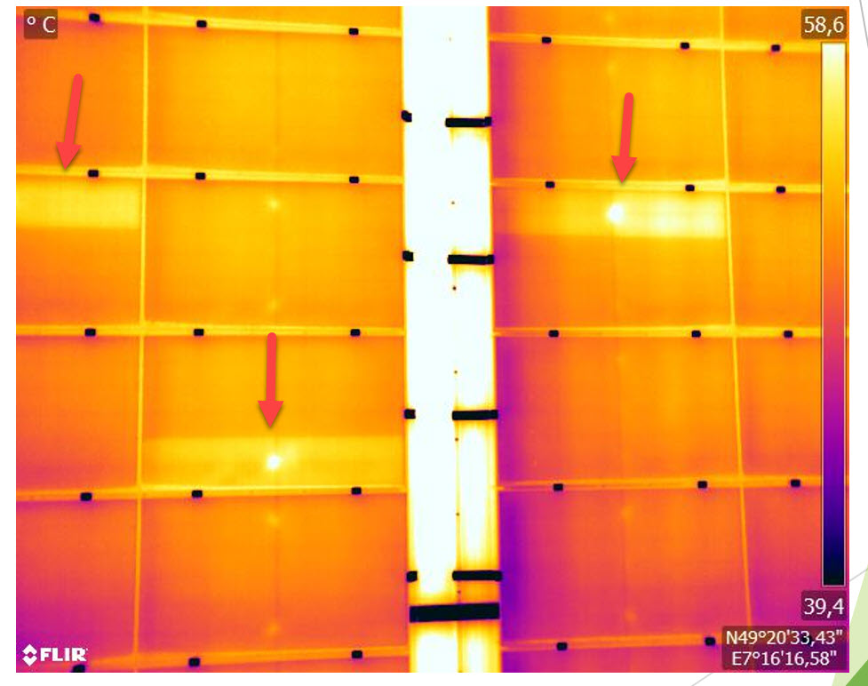
While the open substrings, which are always idle, can be easily found using thermography, the open bypass diodes can only be identified by specifically feeding current into these bypass diode sections. I’ve already described in detail several times here in this blog how to do this at night, for example, with the pvServe.
I recently successfully tested a method to find open bypass diodes even during the day and would like to briefly describe it here.
Find open bypass diode paths during the day
In a short-circuited module string, the substring with the highest short-circuit current always drives the short-circuit current of the entire string. In all other substrings, a portion of the current flows through the bypass diodes that are then active. This fact can be exploited by inserting a power supply into the module string and connecting it in series with the solar modules. The power supply must also have a bypass diode and must be able to drive a current that is greater than the short-circuit current of the module string. The voltage of the power supply must be able to overcome all of the bypass diodes in the module string, which means approximately 1.2V per module or, with 22 modules in series, for example, approximately 27V. I tried exactly this on our PV system here on the roof of the pvBuero and it worked perfectly. The experiment is described in detail in the following video (In german language only).
How often does the error occur?
We find serial defects in larger systems with several thousand solar modules in the thousandths of a percent range. This means that out of 2,000 modules, we find 1-2 affected modules. That may not sound like much at first, but based on the number of modules installed in recent years, one must assume that thousands of such modules have been installed. With open substrings, this initially only leads to a reduction in performance and is not particularly dramatic. With open bypass diodes, these are essentially ticking fire sources that can lead to a fire in such a system at any time.
Conclusion
This is a problem that we as an industry cannot take lightly. Every fire incident is one too many, and we should try to eliminate this problem as quickly as possible through systematic inspection of PV systems. I sincerely hope that this article can make a small contribution to this.
Thanks
My thanks go to my colleagues at pvServicePro (Michael Häusler), pvExperts.co (Ingo Klute), and Prof. Konrad Mertens for providing images, as well as to Daniel Schreiber of Schreiber.Solar for his support with video editing and pvControl (Remy Wedig) for his assistance with measurements. Without the extensive feedback—from our PV expert network and the many participants in our seminars—these articles on this blog would not be possible.