This article describes a typical fault in solar modules which results in a creeping reduction in power output, without the operator noticing this immediately. The phenomenon was already described previously in this blog article. Because it occurs relatively frequently, I would like to explain it again in more detail here.
How solar cells are interconnected
When module manufacturers come up with a new innovation, it is very often because a frequent problem has been recognized on already manufactured modules, and the search for a solution has led to a new idea. This also applies to shingled solar cells, in whose case cell connectors are fully dispensed with, and the solar cells arranged such that they overlap slightly in the module, the previous solar cell’s rear end always being connected in series with the next cell’s front end. Until now, solar cells have always been interconnected in series via ribbons. At this point, one should remember that a classic solar module usually contains 60 or 72 crystalline solar cells connected to each other in series. These connections between the cells undergo extreme, constant thermal stresses during the operation of the modules.
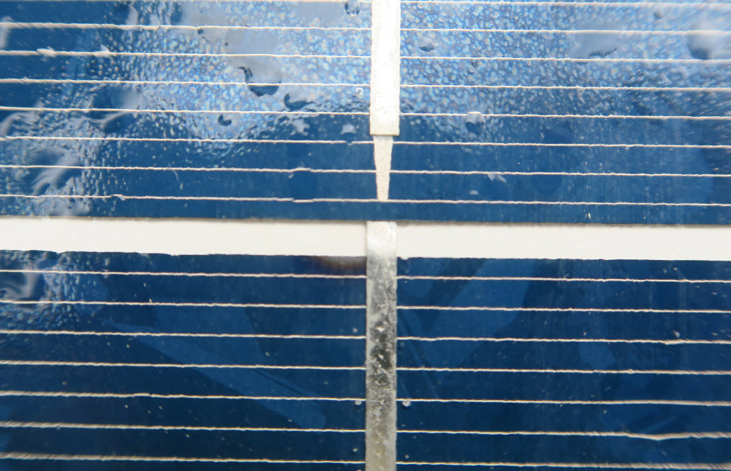
Solar cells heat up to 70°C in summer, and cool down to ambient temperature in winter. In the event of a summer thunderstorm, extreme temperature changes can furthermore occur within in a very short time. Cell connectors usually comprise solder-coated copper with a slightly different expansion coefficient than that of the solar cells themselves. Consequently, any change in temperature leads to mechanical stresses which are normally cushioned by making the connector ribbons sufficiently long, thus leaving some margin for thermal expansion and contraction. In the past, however, this margin was obviously not correctly evaluated by some module manufacturers. Of course, the constant temperature changes are also accompanied by exposure to UV radiation which causes the affected modules’ connector ribbons to tear off eventually.
Tearing of cell connectors is a creeping process
Cell connectors tear off inconspicuously. The cells of older solar modules are usually interconnected in each case by means of two ribbons, just one of which tears off first. In electroluminescence images, this is represented by an unevenness in the solar cells’ brightness. In the case of some cell types with split front contacts, half the cell then turns completely black.
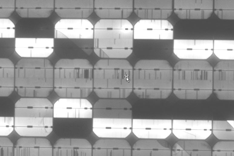
Once the higher current load also causes the cell’s second ribbon to fail, a complete substring of the module, i.e. about one third, is virtually disabled.
Why does an interruption between solar cells not lead to a failure of the entire module string ?
Now one might think that an interruption between two cells should lead to a complete failure of the affected module string, because all its elements are connected in series. This is not the case, though, because every standard solar module comprises 3 sub-strings each furnished with a bypass diode. The affected module therefore does not fail entirely, the bypass diode instead now conducting the current no longer able to flow through the cells.
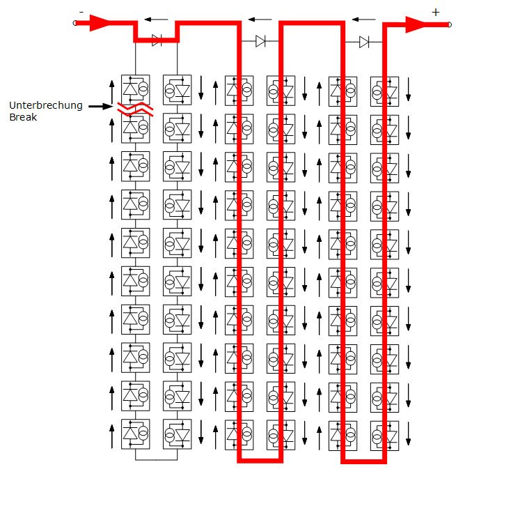
The module behaves virtually as if a third of it were completely shaded. The result is a module whose power is reduced by one third, a module string whose voltage is reduced by one third of a module’s voltage, and a slightly warmer junction box because one of the 3 bypass diodes now operates continuously.
Without careful monitoring, the damage goes unnoticed
The operator of a facility experiencing this problem does not notice anything at first. The inverter continues to feed current into the grid, only at a slightly reduced power. However, because the problem in the affected solar panels constitutes a serial fault, it obviously does not stop at a failure of a single connection between two cells. The process continues until the next sub-string of a module finally fails, and so on.
Often, the operator does not notice the problem until enough cell connectors have been interrupted to prevent the inverter from recognizing a sufficient voltage to operate the module string at the MPP (maximum power point). The reduced output then continues to decrease further, and the problem can no longer be overlooked.
Monitoring is urgently recommended, also for small facilities.
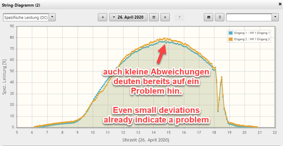
Only use of a monitoring system allows the problem to be recognized at an early stage. Because a photovoltaic system very rarely consists of a single module string, and occurrence of a fault simultaneously in several module strings is equally rare, a very simple diagnostic option is to compare a PV system’s different sub-systems. If the daily curves of 2 module strings are compared with each other as part of monitoring, for example, the specific powers in kW/kWp should always be exactly the same, given identical orientation and inclination of the modules. The emphasis here is on “exactly”. Even slight differences between individual module strings can already be a sign of the described problem. At the beginning, an interrupted cell connection only causes 1/3 of a module to fail. For example, 22 series-connected modules on a roof contain 66 sub-strings. Failure of one sub-string therefore only results in a performance loss of 1/66 = 1.5%.
After the power curves, the second aspect always to be considered during monitoring therefore is the module strings’ DC voltages. A voltage deviation of 10 – 13 V between two strings already indicates a defective sub-string. However, a prerequisite for this is correct MPP tracking of the inverters.
Do not take the problem lightly.
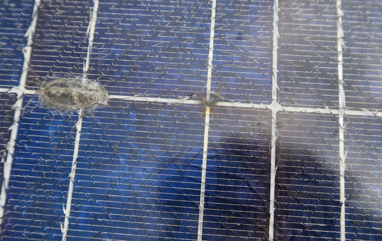
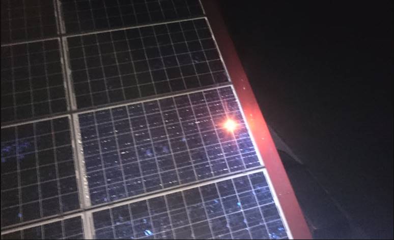
Even if a power loss of 1.5% in a module string seems negligible at first, the problem should not be taken too lightly. Many facilities continue to run for years with this problem, which remains unrecognized at first. However, there have always been cases in which connectors, instead of being torn off completely, have allowed connections to be re-established repeatedly. I personally once witnessed a case in which a connection turned out to be closed during an electroluminescence test at night. We were able to conduct the test normally and found nothing wrong. However, we did not measure any dark iv-curves at the time, otherwise we would have noticed the problem. The next day, at significantly higher temperatures, the connection was interrupted again. This was noticed only because two adjacent inverters fed significantly different specific powers into the grid.
Between the open and closed states, there can therefore be any number of intermediate stages, some of which are associated with a generation of substantial heat. Already observed accordingly have been cases in which the modules’ glass panes were destroyed due to tearing of the cell connectors. In rare instances, electric arcs arise on the connectors and can even lead to fire.

How can the problem be reliably diagnosed?
If a creeping loss in performance is suspected, the problem described here can be easily diagnosed by means of a thermographic examination. If a third of a solar module is in open circuit by an interruption, and the current instead flows through the bypass diodes, this is indicated immediately on a thermographic image by a bright strip equivalent in dimension to exactly one third of a module.
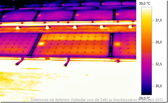
Solar cells in idle always have a temperature 2-4K higher than cells operated at the MPP. If a module with this problem is found, unfortunately it is usually not the only one. Very often, this problem comprises a serial fault which gradually affects an increasing number of modules.
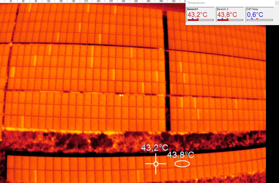
In the case of large facilities with many affected modules, such investigations are now conducted exclusively with the help of drone thermography. However, investigations of this kind should be carried out with the help of experienced drone pilots who not only understand flying, but also know how to analyze the recorded images.
Affected solar modules usually need to be replaced.
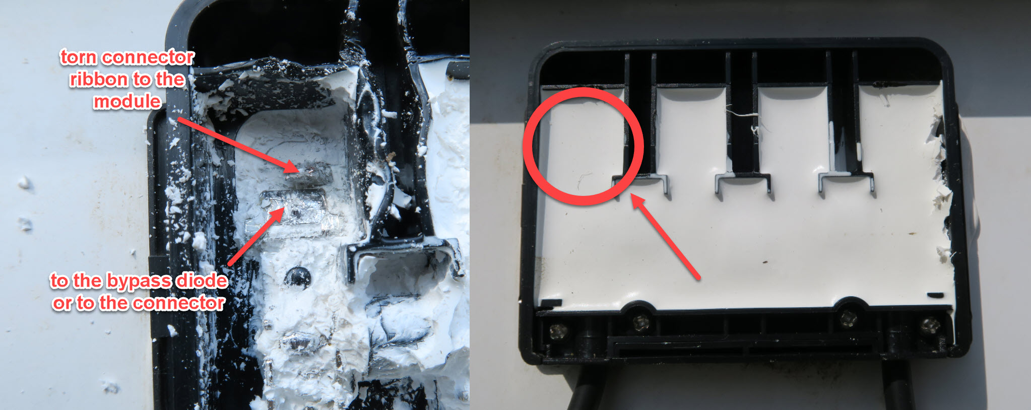
Because interruptions of this kind between the solar cells usually occur within the laminate, they cannot be repaired, and the affected modules must be replaced. In rare cases, however, the interruptions occur between the module’s junction box and the first cell of module’s relevant sub-string.
If the interruption is within the module’s junction box, it might be possible to repair the module. However, this should be done by appropriate specialist companies, so that the problem is permanently eliminated. This applies in particular to potted junction boxes.