
When you measure the open-circuit voltage for all of a system’s panel strings, you should always do so with two measuring devices and compare each string to a reference string. If the difference in voltage is more than seven or eight volts, there is usually a fault somewhere, as I’ve discussed in detail in a previous post. In this article, I’d like to take a closer look at the various faults that can lead to a difference in voltage and how to distinguish them from each other.
In order to understand the typical errors that lead to a lack of voltage for 1/3, 2/3, or even all of a panel, we must first go back to the principles of how solar panels are structured. As the image shows, most crystalline solar panels available on the market today have six columns of cells. Panels with a cell edge length of five inches (12.7 centimeters) generally have six columns of 12 cells, or 72 cells each. The dimensions of these panels are always 0.8 by 1.65 meters. Panels with a cell edge length of six inches (15.24 centimeters) typically measure 0.99 by 1.66 meters and have six columns and ten rows, or 60 cells total. In order to prevent partial shading from bringing an entire panel to a standstill, a bypass diode is connected to each third of the panel; in the case of shading, the bypass diode can then become conductive, reducing the panel’s voltage by one third. I’ve published a number of blog posts about this topic, including several on partial shading and on bypass diodes (not all translated yet). Here, again, is the typical structure of a solar panel:
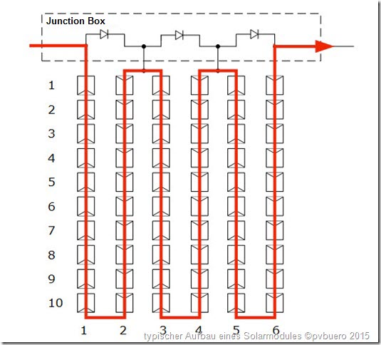
If a panel has a third less open-circuit voltage, that means a difference of about 11 volts (for panels with 60 cells) or 13 volts (for panels with 72 cells) between strings working normally and those that aren’t. Keep in mind, however, that open-circuit voltage varies based on the temperature, becoming slightly lower at high temperatures and slightly higher at low temperatures. The figures mentioned above are generally a good rule of thumb, though; if you want the exact numbers, your best bet is to look at the data sheet, measure the temperature, and then calculate exactly how high the voltage of a third of the panel is using the correct temperature coefficient for the situation.
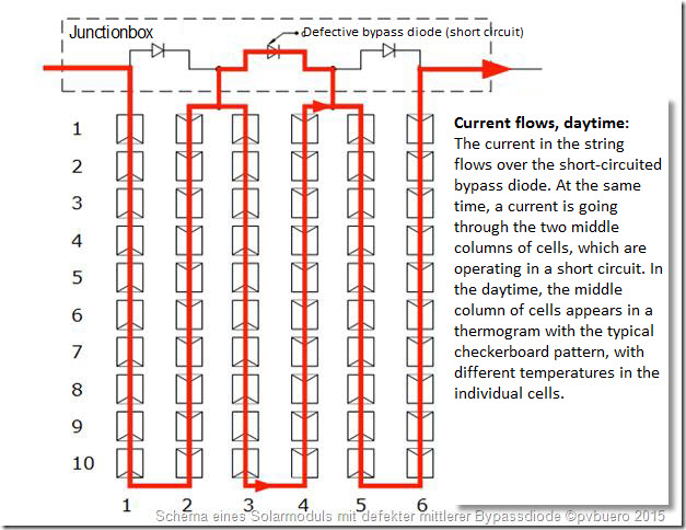
This image depicts the typical case of a short-circuited bypass diode – in this case, the middle diode. The affected panels can be identified in different ways; thermography, for example, shows the typical pattern in which individual cells are much warmer than others in a third of the panel.

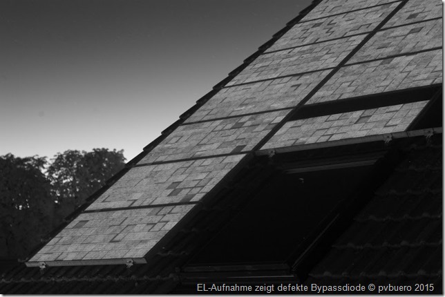
If you analyze the same defect with reverse current thermography, the third of the panel with the defective diode will be about 2-4 K cooler than the other panels in the string with reverse current. Because the diode creates a short circuit, at the defective diode electricity doesn’t flow over the cells, which in turn can’t heat up. In the case of outdoor electroluminescence (EL), the defect appears in a similar way: no infrared energy is emitted from the bypassed solar cells around the defective diode. In the EL image here, the bypass diode on the right of the affected panel is short-circuited.
Why else might there be too low voltage?
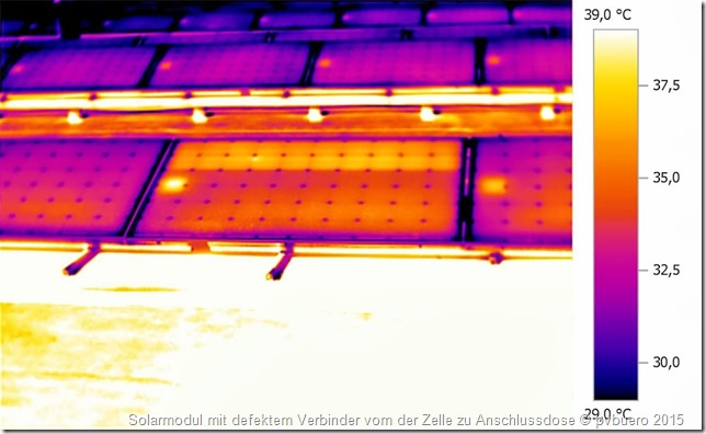
There is also another situation where the affected panel string’s open-circuit voltage is the typical 11 or 13 volts too low but none of the bypass diodes are defective; instead, there’s an interruption between the junction box and the solar cells. In this case, the electricity always flows over the bypass diode because the path through the solar cells is interrupted at some point. The following image depicts this situation.
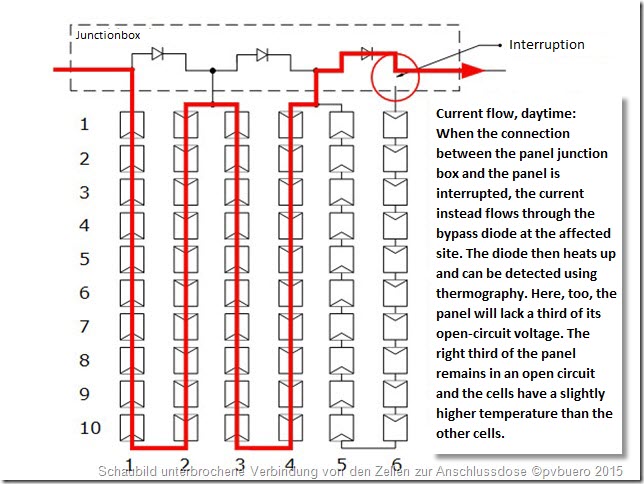
You can easily identify this fault using thermography when insolation is high. The thermogram will show that 1/3, 2/3, or all of a panel is much warmer than the non-defective panels. You’ll also be able to see that the panels sockets have a slightly higher temperature, since all of the electricity flows not through the solar cells but through the bypass diodes at the spot with the defect. In order to understand the image, keep in mind that solar cells in an open-circuit state are about 2-3 K warmer than cells operating based on maximum power point (MPP). This is because, in an open circuit, all of the solar energy that’s not reflected from the panel is turned into heat in the panel; in the case of MPP, on the other hand, some of the energy is drawn from the panel in the form of electricity. As paradoxical as it may seem, this current leads to cooling. Unlike in the case of a short-circuited bypass diode, for this fault you won’t see the typical image with some much warmer cells, like in the thermogram above. Here, all cells in the affected area are equally warm, and the panel socket looks much warmer than its surroundings.
Using the reverse current method, you can detect this fault right away, since the path through the cells is interrupted and the bypass diodes block the reverse current. In the best case, you can sacrifice the bypass diode and increase the voltage until it breaks down. Although this will ruin the bypass diode, it will also identify the defective panel so you can replace it. If the integrated bypass diodes aren’t Schottky diodes (with a cutoff voltage of 50 volts) but silicon diodes with a high cutoff voltage, however, the voltage could be too high for that in the worst case.
Conclusion:
If individual panel strings stand out because their open-circuit voltage is about 11 to 13 volts lower than the other strings, there are a few different possible culprits. In the simplest case, the issue is caused by short-circuited bypass diodes that can be repaired as long as the junction box isn’t encapsulated. The situation is worse when a connecting ribbon is interrupted somewhere in the panel’s laminate and part of the panel is therefore unable to supply current. If this happens, you’ll need to call in a specialist to cut open the laminate, make the connection again, and then apply a repair film. In most cases, though, these panels will simply be replaced.


It’s interesting that my 20 year Sanyo panels have lots of sub-strings within the panel with interrupted traces. Nominally, I would see around 60+ volts Voc, but some panels are 15V, others 30V and some others 45V. I checked most of these panels and the bypass diodes appear to be fine. That would have been an easy fix. Trying to find and fix an interruption is hard without opening up the back of the panel and tracing all the inter-cell connections in the affected modules. I applied a reverse voltage and see no current indicating that my bypass diodes are fine. When forward biased, I see the expected large current. I hate throwing away panels for reasons of poor connectivity. I bet that the individual cells are just fine.
Hi Sam,
if you applied a reverse voltage and no current flowed, there is definitely an interruption between two cells or between the junction box and the first cell. The bypassdiodes are O.K.
Best regards
Matthias Diehl
Hi Matthias,
having started as a maintenance supervisor in one of a big solar plant here in south africa, we have tested low voltages in all the 16 strings connected in an inverter and there is no broken strings or signs of dark spots in the panels. what could be the issue, i am hoping that it cannot be that all the panels are faulty. all the fuses are fine and the panels temperature is okay.
please assist.
kind regards
Godfrey
Hi Godfrey,
what does “low voltages” mean ? Did you consider that high temperatures lead to lower voltages as on the datasheet ?
On reason for low voltage could be PID (potential induced degradation). That can only be diagnosed by thermography or better eletroluminescence.
Matthias
hi,
after I removed all panels, made the construction stronger, replaced all panels, I suddenly have 850 on a string of 10 panels. The only difference I can see is that with the reinstall we tried to prevent cables hitting the tiles etc. so the installer wounded the cable 1 times around before insert the next panel in the mc4 connector. (note the system is not grounded yet). I can only see people having issue with less voltage in the system but I now have 850 in stead of 350… any idea? thanks!
you probably connected two strings in series.