It has already been 8 years since I first reported here in a blog about field tests with electroluminescence, also known as outdoor electroluminescence. A lot has happened in the meantime, such tests now having established themselves as a standard method of fault analysis on photovoltaic modules. That’s reason enough to give another updated overview of what exactly can be achieved through typical use of this method, and what the best possible tests results are.
Before presenting two practical examples of examining PV systems with the electroluminescence method (EL for short), I would first like to briefly introduce and classify this diagnostic method once again. What can be achieved with it when is it used typically, and what are the limits of EL in the field ?
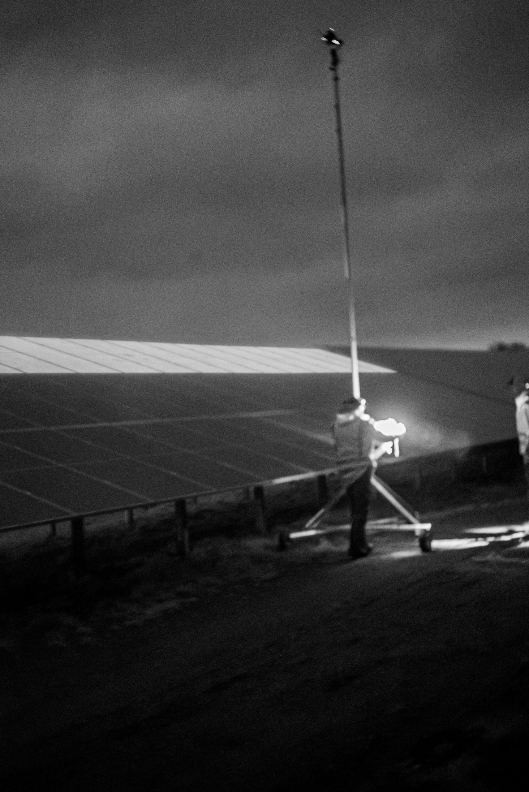
Electroluminescence tests can only be carried out at night to achieve the quality of the EL images presented further below in this document. This is a significant disadvantage right from the start. To allow such tests, the system to be examined entails night-time access and operations.
During measurements, each solar-module string whose quality needs to be checked is energized in reverse by applying a voltage of about 650 mV / cell to the string. The voltage’s polarity is the same as that produced by the string through sunlight during daytime. A string comprising 20 solar modules with 120 half-cut cells accordingly requires a voltage of 60*20*0.65 V = 784 V. Here it is important to note that in modern solar modules possessing 120 half-cells, 60 cells each are connected in series, and 2 sub-strings each are always connected in parallel. If this sounds too complicated, simply take a closer look at the architecture of such solar modules on their respective data sheets or in the related manuals. 784 V are then sufficient to send about 3.5 A in reverse through the solar cells. This requires a power supply unit which can produce correspondingly high voltages, and is preferably portable as well as and suitable for outdoor use.
The described reverse current then causes an emission of invisible electromagnetic radiation in the near-infrared range NIR. This radiation, in turn, can be recorded by means of specially modified cameras, the resultant images providing valuable information about the state of health of the examined solar modules / cells. So much for a brief description of what EL actually is.
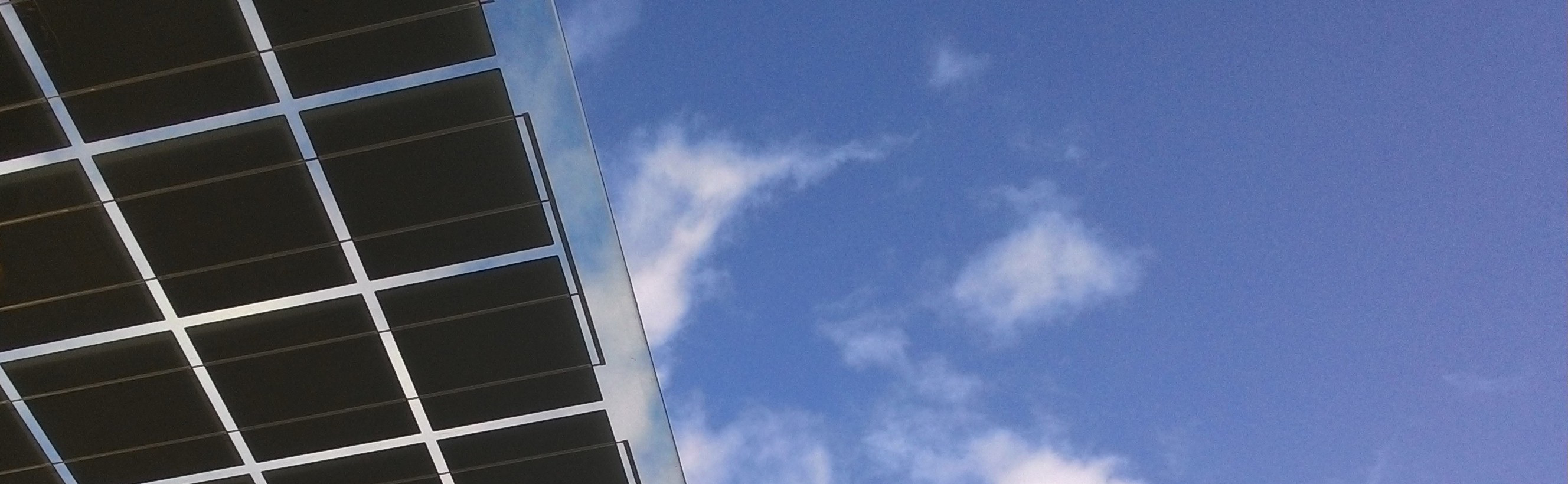
During interpretations of these images, dark cells indicate solar modules’ sections which are less efficient at generating electricity – also during daytime – while bright cells indicate powerful sections. Of course, electroluminescence tests can also detect all module sections which are entirely inactive, for example, due to an overvoltage which has short-circuited the bypass diodes of the affected sub-string.
The degree of detail provided by such EL images has made this method essentially the supreme discipline in testing the quality of PV systems in the field. But as is usually the case in life, these advantages also come with disadvantages. The most important disadvantage -night-time work – has already been mentioned above. In addition, it should be noted that electroluminescence tests are usually carried out on individual strings. This means each module string must be disconnected from the DC power junction box or inverter in order to feed the reverse current subsequently into that string. Furthermore, it is necessary to ensure that the EL camera is in a position from which decent EL images can be obtained. In the case of roof systems, lifting platforms are often used to bring the cameraman as close as possible to the solar modules. Needless to say, such platforms require appropriate positioning themselves. If this is not possible as is often the case, for example, with small house roof systems, an elevated tripod must be used to transport the camera to lofty heights. Some colleagues even suspend the EL camera under a drone to quickly move the camera to the ideal position. However, the EL camera’s decisive advantage of high image quality then suffers from the slightly shorter exposure times entailed during operations beneath a drone.
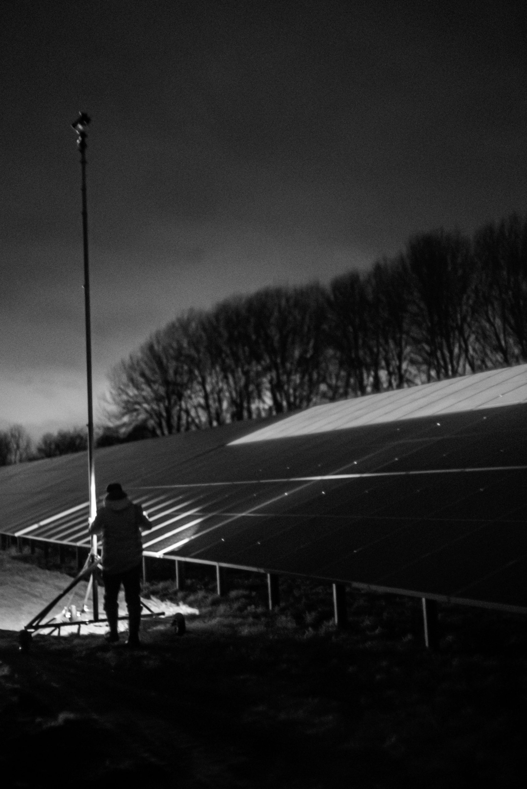
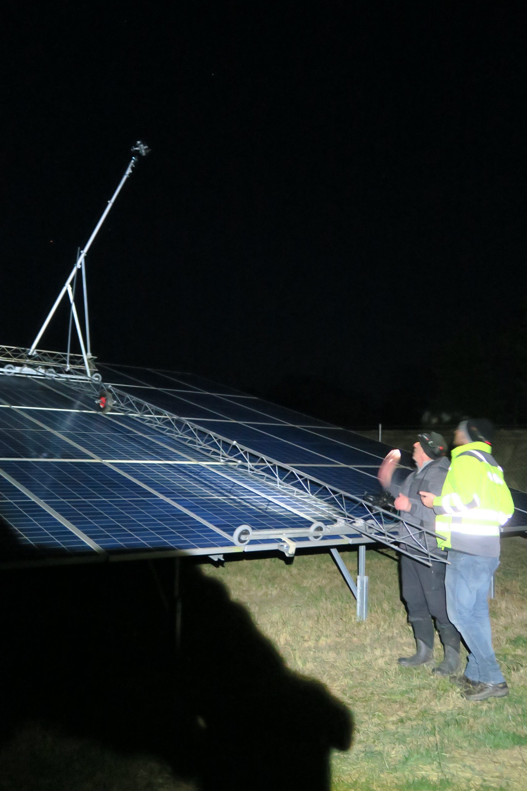
Seen now increasingly at outdoor facilities are large tables on which 3-4 solar modules are stacked edgewise. If each module is already over 2 m long, their fields at parks can quickly attain a depth of 8 m. If upper series of modules also need to be tested whilst maintaining a high quality of results, then some inventiveness is required. This spring we had the pleasure of examining two solar parks jointly with Thomas Reusch from the Messflugservice. As a long-standing partner, Thomas keeps coming up with new ideas on how to master the task described above at large solar parks. The quality of the obtained results has inspired me personally so much that I would like to report on this now.
Used at the first park was a rollable, elevated tripod furnished at the top with a gimbal allowing the EL camera to be moved remotely in all spatial directions. A follow-focus mechanism helps focus the camera at the top of the mast. The camera was remotely controlled via a tablet on which the recording quality could also be monitored.
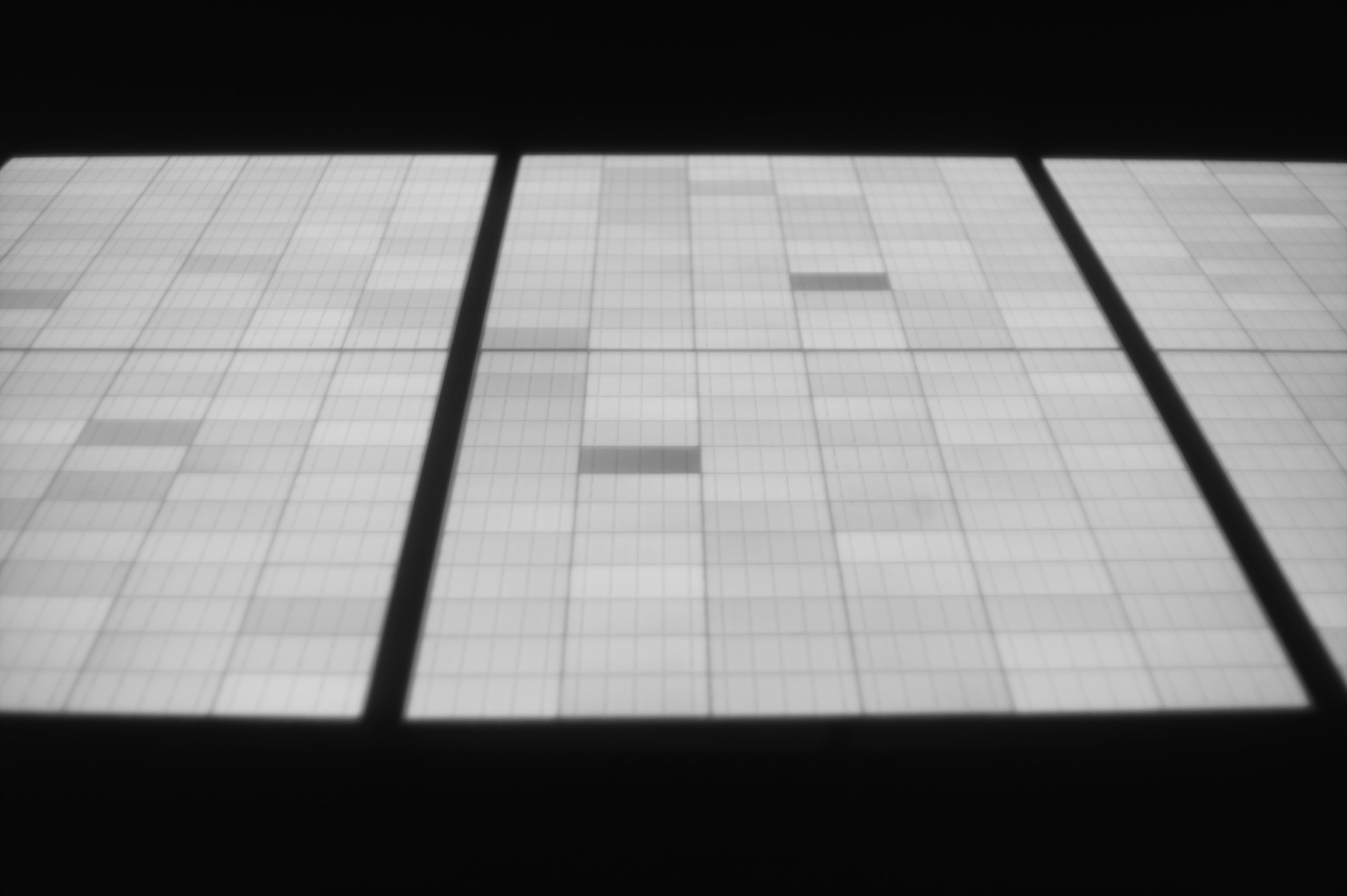
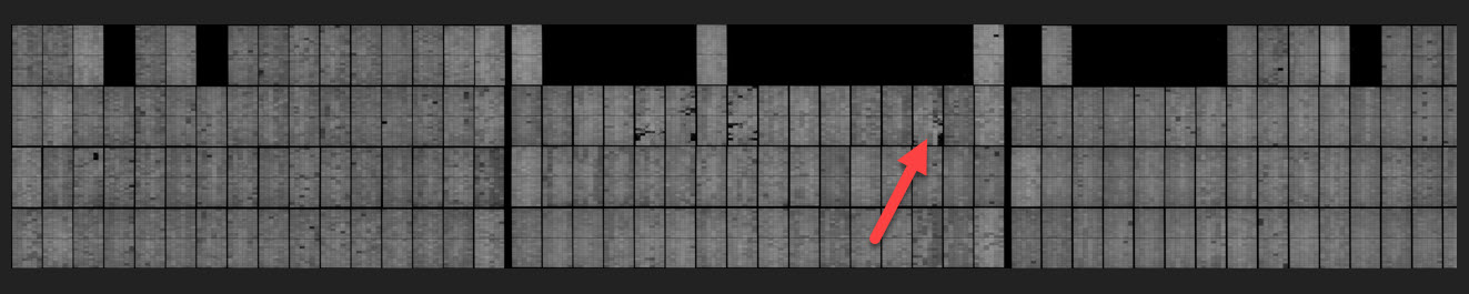
Good individual recordings of the solar modules were possible in this way. To allow simple assignment of detected abnormalities to the respective module positions later, a complex image processing technique was used to combine the obtained images to form a complete module field. The resultant image is quite large but has an excellent resolution leaving little to be desired in terms of quality.
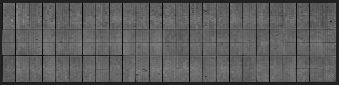
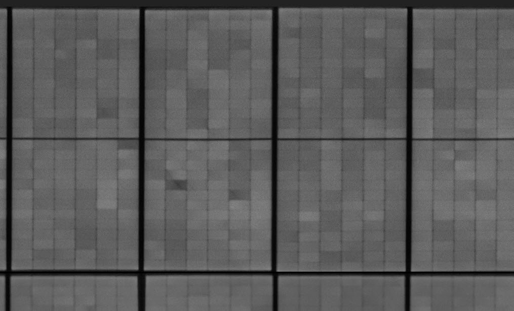
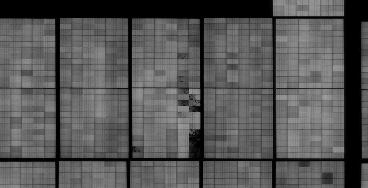
This image comprises a close-up of the previous overview perspective.
The overview perspective exactly reveals the location of the relevant solar module in the field, while the close-up clearly reveals details down to the cell level. Though one may criticize the fact that not every tiny microcrack can be seen in these images, as opposed to laboratory images, the deficiencies which are of relevance to yield and which ultimately matter can certainly be seen.
In another project which is briefly presented here, the module tables were inclined even flatter, so that the distances to the solar modules proved slightly too large even with the elevated tripod. Used here was another special design by Thomas Reusch, comprising a tripod attachment which can be rolled over the module frames. Anyone who initially winces here with concerns that this might damage the cells can be reassured. The tripod attachment slides extremely softly over the module frames in a completely harmless manner. Under investigation here was an instance of storm damage, with the intention of finding out whether – in addition to the solar modules which had flown off – other modules had also been affected.
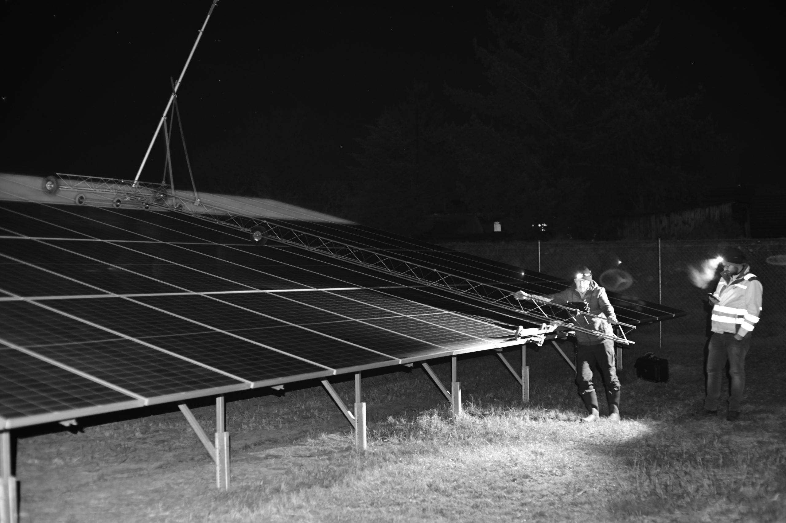
The result was also impressive. All modules could be examined, and minor damage caused by falling modules could be clearly identified and localized.
In summary, the electroluminescence test is now recognized and used as a means of quality assurance by an increasing number of project developers and operators of photovoltaic systems. In combination with dark-IV-curve measurement for early diagnosis of conspicuous module strings, this offers an ideal solution for affordable quality control of existent PV systems without a need to dismantle modules for this purpose. This method is being used more and more frequently, especially during initial commissioning inspections, at the end of warranty periods, and during transfer of ownership of PV systems. If images of such quality are taken after initial commissioning, instances of future damage can very easily be analyzed through subsequent testing and comparison with the new EL images. Discussions with insurance companies about whether established damage is due to a recent hailstorm or was caused already during assembly would therefore become superfluous.


Hi,
We are from the electric testing lab from Ho Chi Minh city, Vietnam.
Now We have plan for invest the EL testing. Could you advice and supply the EL testing equipment?
Thanks
please contact us directly: info(at)pvbuero.de