The VDE 0126-23 Standard now specifies a commissioning test procedure for solar systems. Measurement of the no-load voltage, short-circuit current and insulation resistance. There is now a measuring device, the Benning PV-1, which can carry out all of these measurements in a single pass. The measured values are recorded and the documentation supplied to the customer. But what happens then? Is the data analysed or is it simply filed away? And if it is analysed, what should you look out for? Changes in the voltage of a solar module are mainly due to changes in the temperature of the cells but fluctuations in the irradiance level can also cause the voltage to vary slightly. If you measure a fairly large array with lots of module strings, you will always find variations between the voltages of the individual strands. But how large do these fluctuations have to be before you can safely rule out a fault on the affected module string?
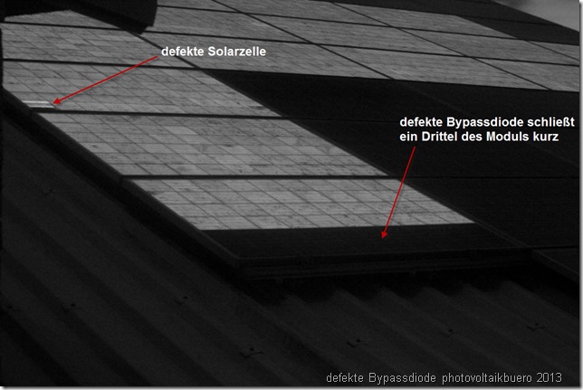
A typical defect, which is sometimes found on brand new modules, is short-circuited bypass diodes. When a bypass diode is damaged by overvoltage, this normally results in a short circuit across the substring of the affected module. As most solar modules contain three bypass diodes, a voltage difference equivalent to the no-load voltage of a third module can indicate a problem. It is also possible, however, that there was a slight fluctuation in the irradiance level when the measurement was taken or that the temperature of the string being inspected was slightly higher than the previous one measured.
The only reliable method of excluding the many influencing factors is to use a very systematic approach. The likelihood of all module strings in a large PV array being faulty is not very high. You should therefore use one string in the array as the reference string. Then take measurements using two measuring devices simultaneously. String 1 and string 2, string 1 and string 3, string 1 and string 4, and so on. All we are interested in is how the no-load voltage we are measuring compares with the measurement for string 1. Any voltage differences found (on strings with the same number of modules) must not be greater than the voltage of a third module. If the difference is greater, faultfinding is called for. The great thing about this method is that it can be used whatever the weather.
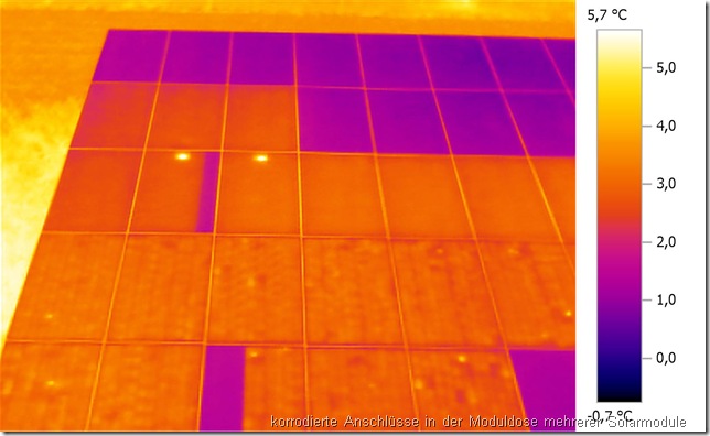
Thermographic analysis of solar modules only makes sense when there is a respectable flow of current. The current causes the voltage to drop where there is contact resistance, leading to power dissipation which heats the affected area. This heat can be picked up with a thermal imaging camera. But what do you do when there is insufficient solar radiation? Come back again when the weather has improved – or make use of the new reverse current thermography method? Reverse current thermography involves feeding a specific current into the module in reverse. A special power supply, such as the pvServe, is needed. A substantially lower current than the module’s nominal current can be used. Just 3A can increase the temperature of specific cells by approximately 2K. Modern thermal imaging cameras can detect temperature differences of 50mK and can easily reveal the difference between energised and non-energised modules. This technology can be used to reliably diagnose initial defects. When a bypass diode is short-circuited, the cells of the affected region of the module are bridged and do not heat up when a reverse current is applied. This makes it easy to identify the problem module.
If a module has poor contact at the cell connectors, for example, you will easily be able to see these as ‘hotspots’ in the thermal image. The beauty of reverse current thermography is that it does not suffer from the ‘false hotspots’ (caused by leaves or bird droppings, etc. on the modules) that can be a problem with traditional thermal imaging. You can distinguish quite clearly between optical and electrical effects.
If you want even more detail so that you can detect even tiny flaws in PV systems, you need to make use of electroluminescence.
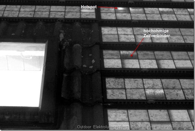
The bad news is that you can only use this technology at night because the light emitted by the solar modules when a reversed current is applied is in the near infrared region. The good news is that you don’t necessarily need an expensive SWIR camera. You can take high quality outdoor electroluminescence photographs with the astro-conversion of a standard digital SLR camera. The only drawback is that the relatively long exposure times require a secure location for your tripod. The great benefit, however, is that you do not have to remove the modules to inspect them. All you do is feed a reverse current into the complete module string and photograph it.


Lets say there is a PV module which is fine (no defects). When one takes a IR image of it when it is in the sun, one would expect a fairly uniform thermal image – no checkerboard and no hot spots. If one would take the same module and remove it from the string and short circuit it and still have it in the sun, how will the thermal image look now? Still uniform? Or checkerboard?
checkerboard. There are always some cells which are worse than others.