The first reverse current testing of solar modules took place some years ago during IEC tests on solar modules. It requires a voltage greater than the module’s no-load voltage to be applied to the module’s terminals. The module then behaves like a circuit with 60 or 72 diodes in series (depending on how many cells are in the module; one cell is the equivalent of one diode). If you slowly increase the voltage above the no-load voltage, a current will suddenly begin to flow in the opposite direction to the “normal” solar electricity. Even when the voltage is increased only slightly, the current will start to grow exponentially, as you would expect from a diode. In the IEC tests carried out by TÜV Rheinland in Cologne, an additional electric current is applied to a module placed in a climate chamber. This tests how climate extremes affect the module while current is flowing. As the climate chamber is dark, this is the only way of simulating the sun. It does not matter that the current is flowing the “wrong” direction when you are checking the electrical connections between cells, and between the cells and the module junction boxes.
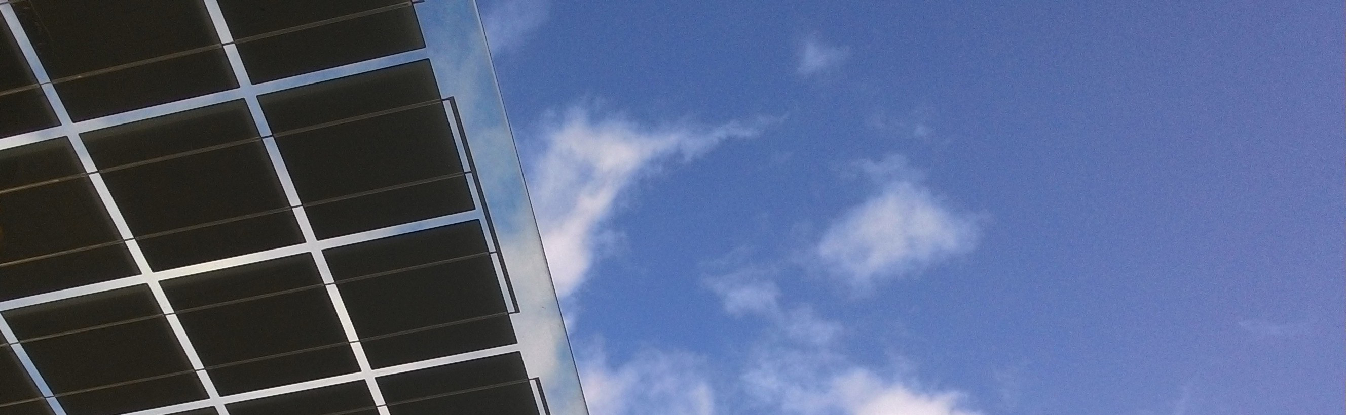
I have written often enough here in my blog about how difficult it is to test a completed photovoltaic system because test methods depend so much on the weather conditions. For example, standards-compliant measurements of a module’s characteristic curve can only be done with an irradiance level of 800W/m² on a tilted module surface. Even thermographic testing for hot spots on cells or junction boxes requires a minimum irradiance of 400W/m², or preferably 600W/m², to ensure an adequate flow of current. These constraints do not make it easy to coordinate appointments with customers, especially when the system is some distance away. We often drive for miles to a system only to discover that the weather has clouded over, making it impossible for us carry out the test as planned.
We were therefore keen to find a way of locating as many problems in a PV array as possible that would function entirely independently of the weather conditions. The idea was to have something similar to the IEC tests, sending current through the modules in the reverse direction. Most module manufacturers now allow for this; some even specify a maximum reverse current figure for their modules.
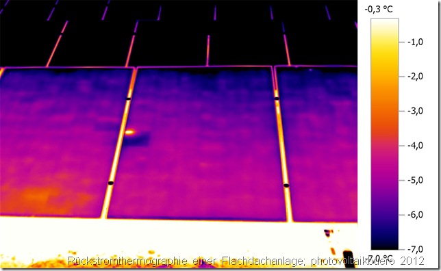
The only hurdle that we still had to overcome was developing a device that could not only apply a reverse current to a single module, but would also work with a module string of, say, 15 or 16 modules in series. The device had to be portable and work in any building with a standard 230V power socket. It shouldn’t use the kind of power that would require a 3-phase supply. In the spring of 2012, we finally found a partner who was able to come up with a power electronics design that suited our needs perfectly. The first practical test began not long afterwards, in summer 2012, and lasted until the autumn. Many of the thermographic and electroluminescence photos we took during this time have already appeared here on this blog.
![]()
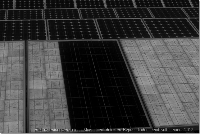
The results exceeded all my personal expectations. I was particularly please with the facility for taking electroluminescence photos. Each time I saw the results it made me smile and shed a tear at the same time, as I found small faults with virtually every array we inspected. In some of the systems the faults were actually not that minor. Although most of the pictures were taken at night at first, we discovered that reverse current thermal imaging can deliver excellent results during the day as well (although the electroluminescence imaging only works at night at the moment).
Thus, the idea for pvServe was born. The first service power supply for the photovoltaics industry, the technical specification of which I am delighted to publish here for the first time:
- Udc: 0…1000V
- Idc: 0…5A
- Pdc: 3300W
- Uac: 230V (connected to a normal 230V power outlet; 16A)
- Weight: 18.5kg
- Case: 19″ 4u flight case
- H x W x D: 56.5 x 22 x 58cm
- The plus and minus connections are via 2 test sockets (subject to modification)
Power has been deliberately limited to 3.3kW in order to enable operation via a conventional 230V mains supply. At 1000V DC, the device is therefore limited to 3.3A. At 5A for Idc, the maximum voltage is 660V.
The number of modules that the device can apply a reverse current to depends, of course, on the number of cells. Apart from that, a higher voltage is needed at low temperatures than at high temperatures.
The following values are offered as a guide. At an ambient temperature of 20° you can apply a reverse current to approximately 22 modules with 60 cells in series or 19 modules with 72 cells in series. (at 1000V)
Using the higher current of 5A, you can test 17 x 60-cell modules or 15 x 72-cell modules.
3.3A is the equivalent of about 66% of the nominal current of a modern 72-cell module with 5″ cells. You are therefore more or less simulating incoming solar radiation of 660W/m2. With a 60-cell unit with 6″ cells this is still just under 40% of its nominal current or a solar radiation intensity of 400W/m². As modern thermal imaging cameras are able to reveal temperature differences of up to 50mK, this current is sufficient to localise most faults.
At this point I would like to provide a quick bullet-point summary of all the things you can do with the power supply.
- Reverse current thermography troubleshooting
- Reverse current thermography to localise roof-mounted module strings without relevant documentation
- Outdoor electroluminescence
- Bypass diode tests
- Inverter start-up tests prior to installation of the solar array
- Reversing PID (Potential Induced Degradation)
- Thawing snow on solar modules to enable it to slide off more quickly
pvServe will be available from us from February 2013. The package contents include the power supply, two test cables fitted with MC 3 plugs, 2 test cables with MC 4 plugs and a power outlet socket. Delivery time is approximately 4 weeks.
If you have any questions, we’d be happy to answer them here via the blog, in our forum or by email.


Hi:
How much is the price of PVSERVE?
You can get a quotation from our Mr. Henning: mh(at]pvbuero.de (Tel.: 0049 6142953047-7)