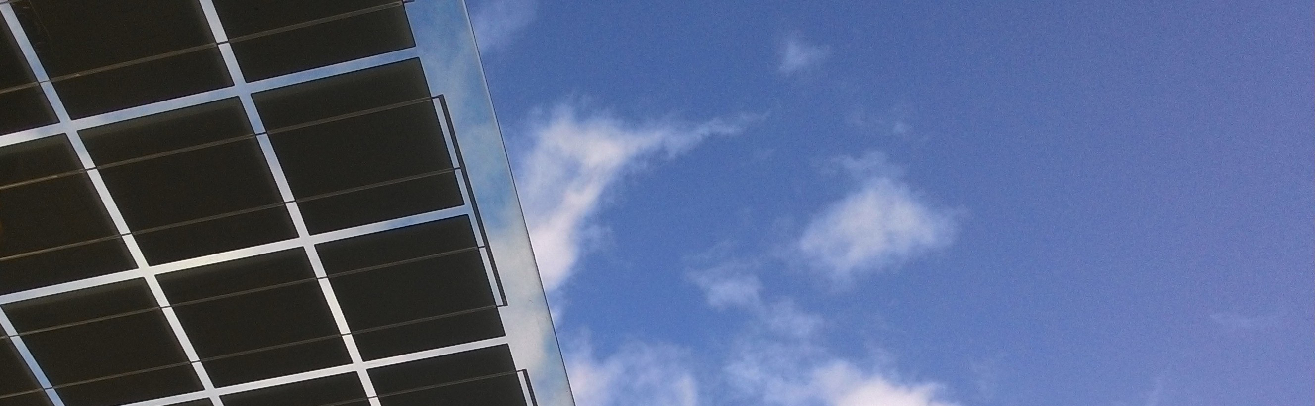
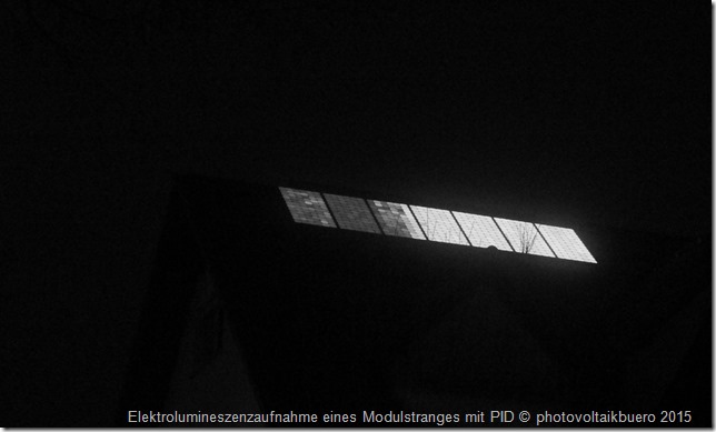
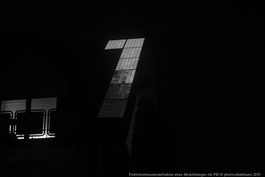
Potential induced degradation affects many solar power arrays by reducing panel performance more and more over time. Although some types of PID are reversible, others are not, and those are therefore a permanent problem for the affected modules. This article describes the causes of PID, how to detect it, and how to prevent it. All electroluminescence images in this paper were created using pvServe.
The best known case of PID is the polarization effect seen in the first batches of high-performance panels made by American manufacturer SunPower. Under certain conditions, the panels lost as much as 30 percent of their rated output (watts-peak) within a very short amount of time. As it turned out, the issue had to do with the solar panels’ potential to the ground and could be prevented by grounding the solar generator’s positive pole. This solution even largely reversed PID in arrays that were already affected.
But what is a panel’s “potential to the ground” exactly?
In solar modules connected in series, the same current flows through all of them, so the voltage increases with each panel in the chain. In electrical engineering, voltage is defined as the difference between electric potentials. To make it easier to understand, non-specialists are often invited to think of gravity instead of electrostatic force (Coulomb force) and compare electric voltage to a difference in altitude on a mountain. A hiker in a chalet at 1,500 meters has a higher (gravitational) potential than a second hiker on a path at 1,000 meters. In other words, the hiker at 1,500 meters has greater potential energy than the one at 1,000 meters. The energy difference between the two hikers does not depend on absolute altitude and would be the same if one were at 1,000 meters and the other at 500 meters. The difference in potential is all about the difference in altitude.
The same is true of Coulomb force in electrical engineering: voltage – the difference in potential – doesn’t tell us anything about the absolute value of the potential. Even if we know that a solar power array has a voltage of 600 volts between the positive and negative poles, we don’t know whether the positive and negative poles have, respectively, 300 and -300 volts, 600 and 0 volts, or 900 and 300 volts. Generally, though, ground potential is defined as a reference potential of zero volts.
For a photovoltaic array, the value of the absolute potential (to the ground) at the positive pole, at the negative pole, or somewhere in-between depends greatly on the inverter’s topology. In addition, an array’s absolute potential does not necessarily remain at one level but can change constantly while in operation, also depending largely on the type of inverter and its internal connection concept. The general rule here is that we can only set a photovoltaic array’s potential to whatever we want if we install an inverter with a transformer. In a low-voltage system, the neutral point of the local network transformer is generally on the ground; the N conductor therefore has ground potential. In the case of a transformerless inverter, the different mains phases alternate between being connected to the array’s positive pole and negative pole (to put it very simply). The positive and negative potential to the ground is therefore constantly changing. If the negative pole or the positive pole is grounded in a solar power array with a transformerless inverter, the inverter’s output stage could be short-circuited under certain connection conditions.
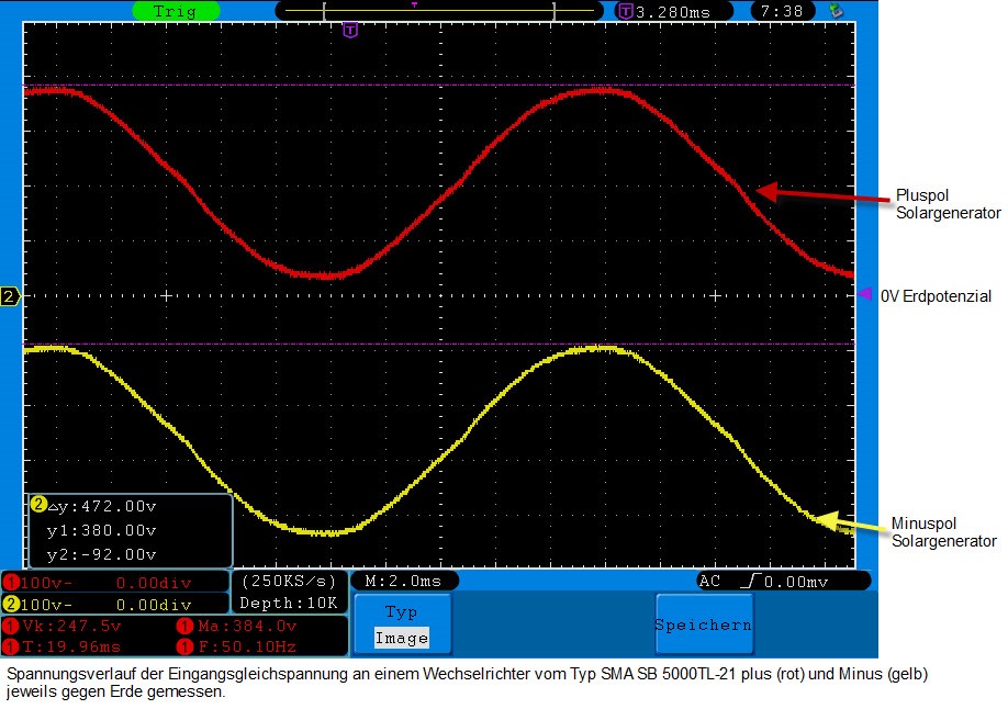
As a result, a transformerless inverter generally results in parts of a photovoltaic array having positive potential to the ground and other parts having negative potential to the ground. So along with voltages between an array’s positive and negative poles, there are also always voltages between individual solar cells and the ground. If an array’s substructure is grounded in line with requirements, these voltages are then directly between the cells and the panel frames or the panel clamps. The oscillogram above depicts voltage over time for the positive and negative poles of a photovoltaic array with an SMA SB 5000TL-21 inverter. Note that the direct-current voltage for this type of inverter fluctuates around the ground potential of zero volts at a frequency of 50 hertz. (The direct-current voltage from the array is the difference between the red and yellow lines.) Note also that there is some asymmetry. One way to put it is that out of all of the solar cells in a string of panels connected to this inverter, the majority of the cells have, on average, a negative voltage to the ground, while a smaller number of cells have, on average, a positive voltage to the ground.
The potential of the frame and that of the different cells are separated from each other with isolators, i.e. materials that do not conduct electricity (or, actually, only conduct it very poorly). Key here are material properties that are already well known in other areas of technology – that is, how isolators react when they must constantly deal with direct-current voltage. If you ask, say, capacitor manufacturers, they will tell you that tiny leakage currents flow between the two capacitor plates, including currents that change the material in a dielectric polarization process. Let’s say you have a capacitor that has been charged for a long time. If you short-circuit it (that is, discharge it) and then open the short circuit, you’ll be able to measure residual voltage soon thereafter because of how the insulation material’s molecules are oriented in the electric field. This residual voltage depends to a large extent on the isolation material used and should generally be as low as possible. When it comes to isolation materials for high-voltage cables, too, such effects have been recognized and are divided into different types of residual currents – the dielectric absorption current, the leakage current itself, and in some cases a capacitive charging current.
Depending on the isolation materials used, tiny leakage currents can also occur in photovoltaics, making a path from the panel frames and substructure to the cells or in the opposite direction. These currents are dependent on the potential of the cells to the ground and, therefore, on the topologies of the inverters used. In some cases, over time these tiny currents can build up electric fields that weaken the fields within the solar cells, or they can cause ions to build up in a cell’s crystalline silicon grid and lead to local short circuits from the cell’s positive pole to its negative pole. These situations result in decreasing voltages at the solar cells and, in turn, efficiency losses.
SunPower, the panel manufacturer mentioned earlier, quickly figured out how to overcome this problem: the array must be galvanically isolated from the grid, and its positive pole must be grounded. A technical rule formulated for the first generation of SunPower panels therefore stipulates an inverter with a transformer and positive grounding. This solution ensures that all of an array’s solar cells will always have a negative voltage to the ground and therefore that electrons can always go from the cells toward the panel frames but never in the opposite direction..
As time went on, people noticed that this problem not only occurred with SunPower’s rear-contact solar cells, but also with other cells with conventional front contacts. When considering how to face this problem, however, another property of the solar cells plays a role, as well. SunPower cells are made out of a wafer that has already been n-doped; it is then p-doped in a subsequent step. Most standard panels these days, on the other hand, still use wafers that are p-doped with boron, with n-doping added to the front side afterwards. In other words, the internal electric field’s direction is exactly opposite in the standard cells compared to the SunPower cells – and the PID effect can be prevented with a solution that is also the exact opposite. In the case of modules (with p-doped wafers) in danger of suffering PID, the array’s negative pole must be grounded so that all cells have a positive initial voltage to the ground. Here, too, the PID effect can usually be almost completely undone. If the “healing” process needs to be sped up, instead of grounding the appropriate pole, an option is to short-circuit the positive and negative poles (that is, bring them to a potential) and then use an external voltage source for 1,000 volts to the ground. Panels with n-doped wafers require -1,000 volts, while panels with p-doped wafers require +1,000 volts. The effect will disappear again after some time.
Nowadays, a lot of panel manufacturers (including SunPower) know how to handle PID and can protect against the effect with suitable embedding materials. But up to now, many panel types could only be used if the inverter had a transformer and a pole was grounded on the DC side; now, they can be used even with transformerless inverters.
How to detect PID
A panel string with PID has a much lower open-circuit voltage than one without PID. The first indications of PID can therefore be found in the comparative measurement of open-circuit voltages described here (translation will follow…). PID typically affects only one end of a string – the positive end for panels with n-doped cells and the negative end for panels with p-doped cells. Therefore, if you’re able to measure the open-circuit voltage for each panel in a string and it continues to decrease as you approach the end of the string, you may very well have a case of PID. Often, however, panels are not easily accessible, leaving only outdoor electroluminescence – as shown in the two images in this article – as a method for detecting PID.
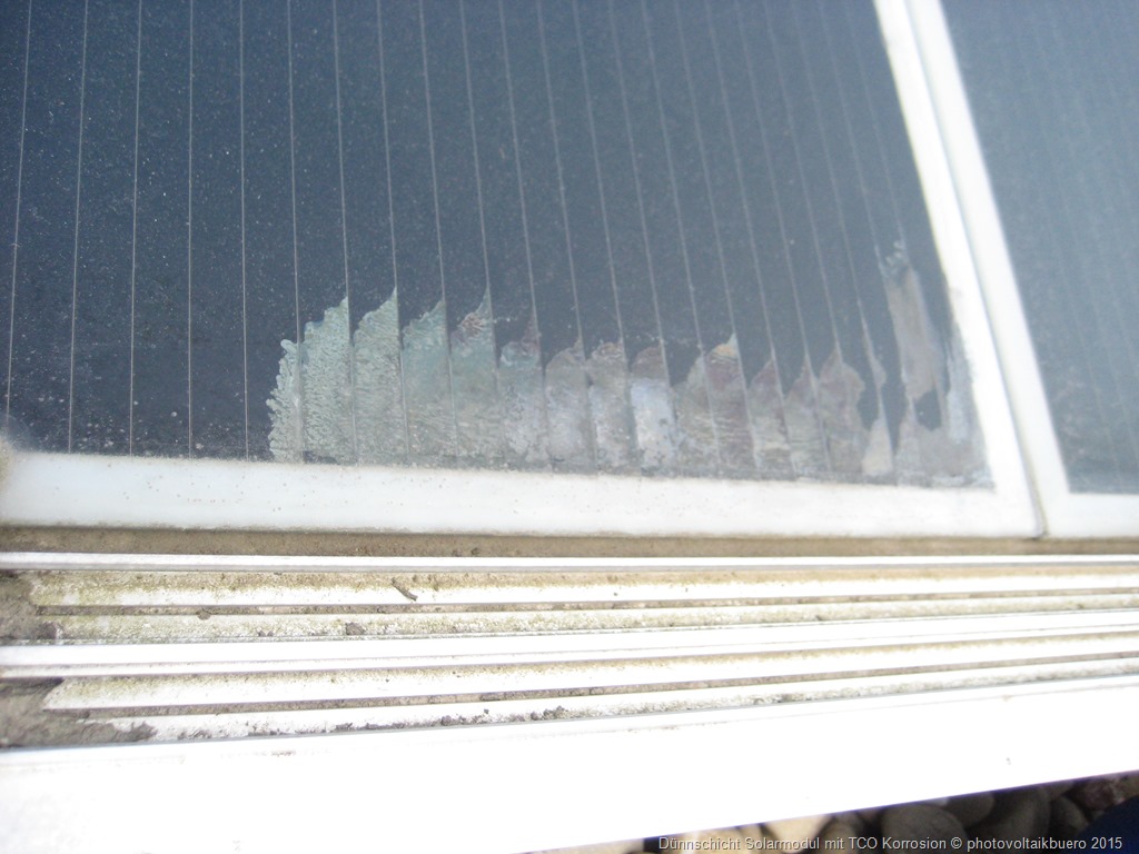
Non-reversible PID
Thin film panels can also suffer from non-reversible potential induced degradation – a type of electrochemical corrosion known as TCO (transparent conductive oxide) corrosion that affects the thin layer on the front of the thin film panel around the panel clamps, especially at the negative end of the panel string. As time goes on, the cell increasingly loses its ability to remove charge carriers and degrades more and more.
An important note to finish on is that high temperatures and a humid climate increase the likelihood of PID.


Kommentare