When I was writing this article, I had to keep reining in my annoyance, because I didn’t want anyone working for an inverter manufacturer to stop reading before they had even finished the introduction. Today, I’d like to talk about the DC connector compartments on solar inverters and ask the manufacturers: what on earth were you thinking of when they designed them? This is an open letter from a frustrated service engineer to the world’s inverter manufacturers.
Dear Inverter Manufacture,
The DIN EN 62446 standard has been around for many years. It specifies precisely which tests have to be carried out when commissioning a photovoltaic system and during subsequent re-inspections. Large PV arrays of over 100 kW generally require re-inspection once a year, and smaller ones once every two years. On the DC voltage side, the standard requires measurement of the open-circuit voltages and the insulation resistance of all module strings. All testing carried out on photovoltaic systems for the purpose of finding faults in the solar modules must also include measurements at string level. This applies whether you are measuring the IV curve, determining the STC power of a module string, carrying out electroluminescence tests or reverse current thermography, or locating wiring open circuits with the aid of our pvTector.
In all of the above scenarios you need to access the individual module strings of the PV system in order to carry out your investigations. You therefore have to get to the DC junction box, or as is usually the case when dealing with string inverters, gain access directly to the inverters on each individual module string – and not just once when commissioning the system, but every subsequent year or other year. When you look at the design of many inverters specifically from the point of view of DC connector accessibility, you can’t help feeling that many manufacturers are blissfully aware of this particular state of affairs.
Is it really that difficult to produce a design that allows you to:
- isolate the DC side with an easy-to-reach DC switch,
- access the power supply’s DC connectors in a few simple steps (perhaps using specialist tools – no problem with that),
- disconnect the parallel circuit of several module strings at the inverter input without too much fuss, so that you can
- easily and quickly connect your measuring instrument to the test terminals provided for the purpose and carry out the necessary measurements in a few minutes?
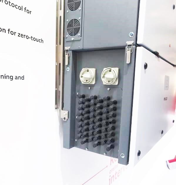
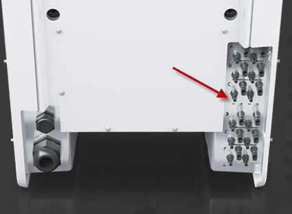
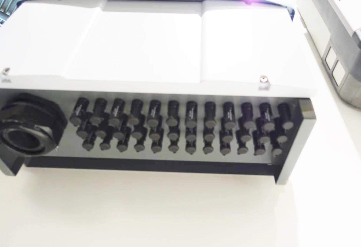
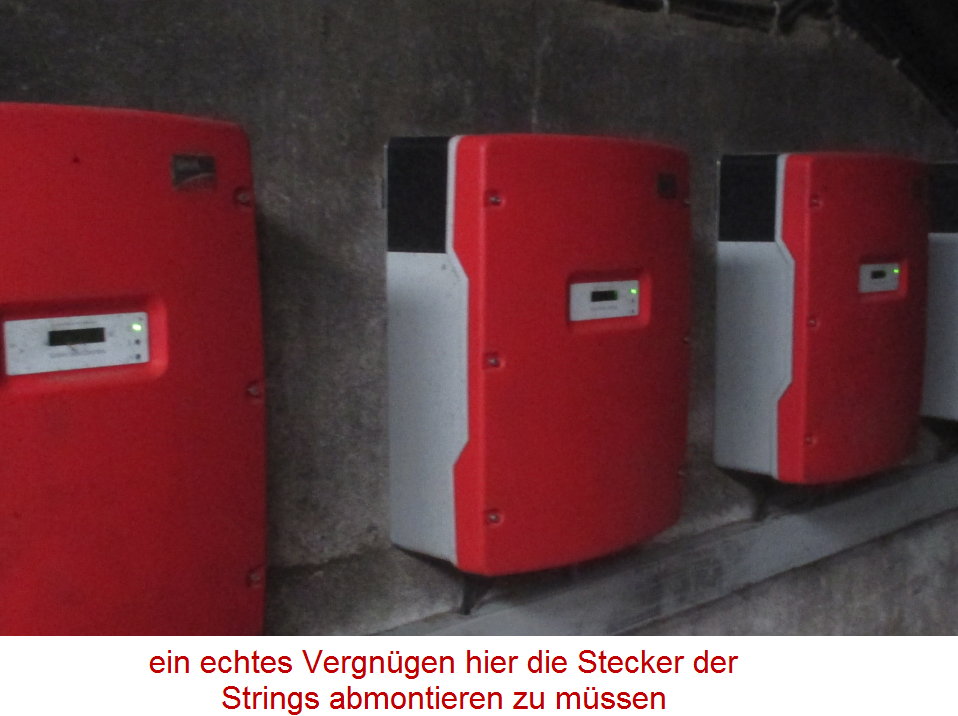
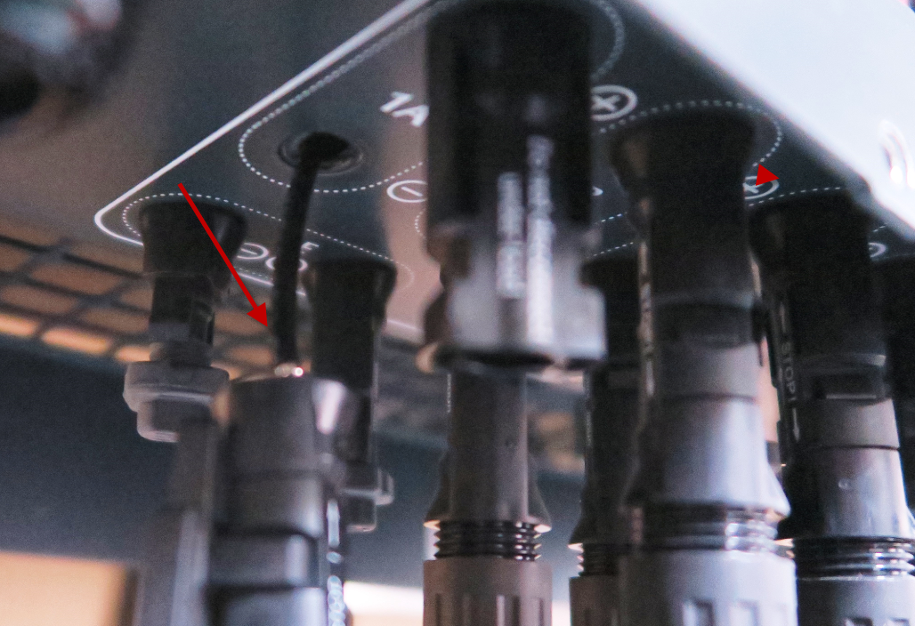
OK, so it was only a dream. Unfortunately, reality – in which you first have to struggle with practically inaccessible connectors (Stäubli MultiContact, Phönix Contact or whatever) – looks somewhat different. The plugs are difficult to get to, and much too close together, and often laid out in such a ridiculous way that you cannot easily reach them even using the manufacturer’s tool. Of course, one of the plugs is always so dirty and misshapen that it simply refuses to budge, no matter how much force you apply.
You won’t find many inverters installed in cleanrooms. More often than not, you’ll find them in places like cow sheds, warehouses and factory buildings and, of course, outdoors.
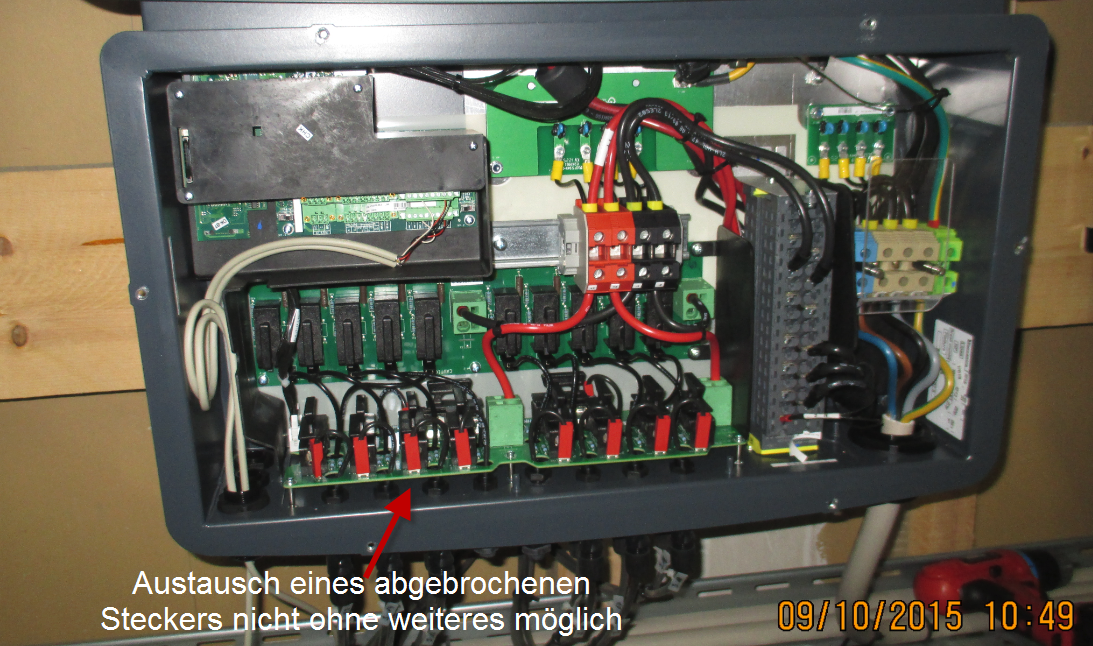
While we’re on the subject of applying force… if a less patient installer or service technician worked on the system before you arrived, don’t be surprised to find one of the connectors broken off and rolling around in the case. Another clue would be the insulation fault caused by the connector making contact with the inverter case.
Unfortunately, one of the first jobs you have to do when carrying out a re-inspection is to repair these broken connectors. You can install a new connector if you have the right spare parts and if installation is in fact possible once you have opened the case cover.
I clearly recall the smiling sales person from the connector manufacturer telling me at Intersolar how easy these connectors are to unplug. And I didn’t find it at all difficult – on the exhibition stand. But when you are on a ladder 3 metres up, working on a system with 60 connectors, 56 of which are easy to disconnect, yet 4 will not move for love nor money, you are likely to experience the same extreme frustration that led to the writing of this article.
Once again, clearly and concisely for everyone’s benefit:
- There should be an acceptable amount of space between each of the connectors on the inverter.
- The connectors should be easy to access and not require you to undo six screws, because you can guarantee that at least one will have a stripped head when you are called out to it.
- The connectors in the case should not be angled to the rear, preventing any normal human being from inserting a tool to undo them.
- It should be explained to installers that locating a cable conduit directly under the inverter makes it impossible to access the connectors later.
- It should be possible to disconnect string 8 without having to disconnect strings 1-8.
- Being able to carry out measurements without having to unplug any connectors at all, as outlined earlier, would be the ideal scenario.
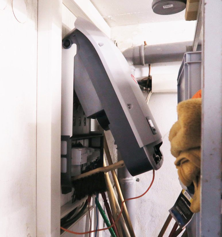
- You should be able to access the connectors without having to resort to using a broom handle or a metre stick (see photo below).
- And a word to installers. We need to access these connectors on a regular basis and would be really pleased if we didn’t have to lie in the mud or crawl around in the dirt while doing so. Also, trying to unplug one of these infernal connectors is a lot more pleasant when you are on the ground rather than balancing five metres in the air on a ladder.
So, dear inverter manufacturers, please don’t take this personally, but would you mind having a word with your installers and also do some research into the connector problems I’ve just described. Think for a moment of the lacerated, bleeding fingers that are now an inevitable fact of life for all engineers who do battle with inverter connectors whenever they make a service call.
Then dig deep into your inner selves. I am sure you can find a way of making my dream come true. You have the power to make re-inspections a breeze for every installer and installation engineer, and to make re-inspections something that they actually look forward to.
And if you’d like to do something really clever, take a look at what your Asian colleagues are doing: making inverters that allow you to measure complete IV curves.
In future, why not make inverters that you can switch into service mode, preferably remotely? The inverters would then carry out the measurements automatically and send the results for all module strings to a data portal. Then we wouldn’t need to unplug connectors or stand around on ladders making the air turn blue…
Regards, your extremely exasperated service engineer nursing freshly cut fingers – again.
Matthias Diehl
PS And don’t even dare to submit a device for an innovation prize that doesn’t take on board my dream checklist. Thank you.
PPS If fellow-sufferers feel the need to share their connector experiences, or if inverter manufacturers would like to tell me I’m too dumb to unplug a connector, the comments area under this article offers you this very option. Let the discussion commence!