The search for defective bypass diodes has been a frequently discussed blog topic here. Just when I thought I had already described typical thermograms and electro-luminescence recordings in detail, fellow drone pilot Thomas Reusch notified me of a case which we then jointly pondered. A small experiment in the garden behind our office made it possible to ultimately explain the phenomenon, which will be described in this article.
The ability of overvoltage and lightning to short-circuit bypass diodes is now known. The reason for this will be described here again briefly.
In the dark, each solar cell acts as a diode. The maximum reverse voltage of this diode is 14 – 15 V, and its normal current flows in the reverse direction in the presence of light. Because this situation is not necessarily intuitive, it needs to be mentioned again explicitly at this point. If the current flowing through such a diode exceeds the generation current, the diode again assumes a reverse-bias (refer to the unknown ranges of a solar cell’s characteristic). In a standard solar module, 20 such series-connected diodes are always connected in parallel with one bypass diode. Only a voltage of 0.4 – 0.5 V is necessary to drive a current through the bypass diode, whereas larger currents cause a voltage drop of 280 – 300 V across the 20 cells (1/3 module).
This situation can be clarified and explained once more by considering the following postulate:
The 3 bypass diodes of a standard solar module with 60 crystalline 6″ cells are removed. The module is then placed in bright sunlight. The module would now able to deliver 8.5 A. An external source capable of supplying a much larger current, e.g. 20 A, as well as very high voltages is then connected. This source must drive the current through the module in the forward direction, i.e. the same direction in which the generated current would flow. A voltage in excess of 900 V would be needed to push these 20 A through the module. Either this experiment can be considered purely in theoretical terms, or an actual test can be conducted using an old module. After the experiment, the cells will probably be nearly finished because of having been operated in the “breakdown” range.
In the event of a lightning surge current amounting to several kA (kilo-amperes), most of the current always flows via the bypass diodes for the reason mentioned above, and usually destroys them. Often, the diodes are then shorted and act as a surge protective devise on the solar cells.
We have often studied PV systems in which only a few bypass diodes of an affected module string were still OK. All others were either fully burned open, or shorted. The cells are very often undamaged, and work again after the bypass diodes have been repaired.
In the electro-luminescence recording, such routes comprising shorted bypass diodes can be easily demonstrated because the affected substrings of the respective modules no longer exhibit any electro-luminescence.
A second method of finding defective modules is thermography. In this blog post regarding short-circuited bypass diodes I have already described in detail how a typical chequerboard pattern of warmer and colder solar cells is then always exhibited by the affected substring. The term “chequerboard” should not be taken here literally, however. Of course, not every alternate cell is always warmer; instead, there are poorer cells which can drive a lower short-circuit current, and there are better cells, both being distributed more or less randomly in the substring. Now consider the thermogram which was mentioned at the start and meant to help diagnose damage presumably due to overvoltage. However, no typical “chequerboard pattern” could be found in the diagram. Instead, numerous strangely hot cells were to be seen at the bottom edges of the modules.
What happens if a heavily soiled solar module is shorted?
When a solar module or bypass diode is shorted, not all the cells are shorted. Though the voltage of the sum of the cells in the electric circuit is 0 V, the voltage of the individual cells deviates significantly from 0 V in some cases. The cells with lower short-circuit currents become consumers, while the cells with higher short- circuit currents become producers. There is therefore a shift in power from the “better” to the “poorer” cells. In the case of a normal solar module, the “poorer” cells are statistically distributed evenly across the module (chequerboard pattern). This is not the case with a heavily soiled solar module.
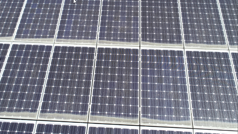
The warmest cells here are those which can drive the lowest short-circuit current; logically, these are the most heavily soiled cells. A shorted bypass diode here therefore does not exhibit the typical chequerboard pattern, but a strip of warm cells where the most dirt has accumulated. In the case described earlier, this is the bottom edge of the module. Unfortunately, these heavily soiled cells also heat up when the inverter reduces the voltage and the respective bypass diode becomes conductive. In the thermogram, this situation can hardly be differentiated from a full short-circuit across the bypass diode. It should be pointed out here that a voltage of approximately 0.5 V drops across a conductive bypass diode. The voltage drop across a shorted bypass diode is ideally 0 V. The difference is therefore conceivably small. If all shorted bypass diodes need to be clearly identified in the case described above, the inverters must therefore be switched off so that all modules are in idle. A current flows only where the bypass diodes are shorted, which is also only where soiled cells at the bottom of the module become hot. I would guess that one string in the illustration above is idle. Unfortunately the entire system was not switched off in the case above.
This fine example is further evidence that a clear interpretation of a thermogram is only possible if the operational state of the solar modules recorded by the thermograph is known. Certain faults such as open cell connectors (see this article in the blog) in which case a third of the module is idle, are found only during MPP operation. Shorted bypass diodes can be found much more easily in idle, when the inverter is switched off.
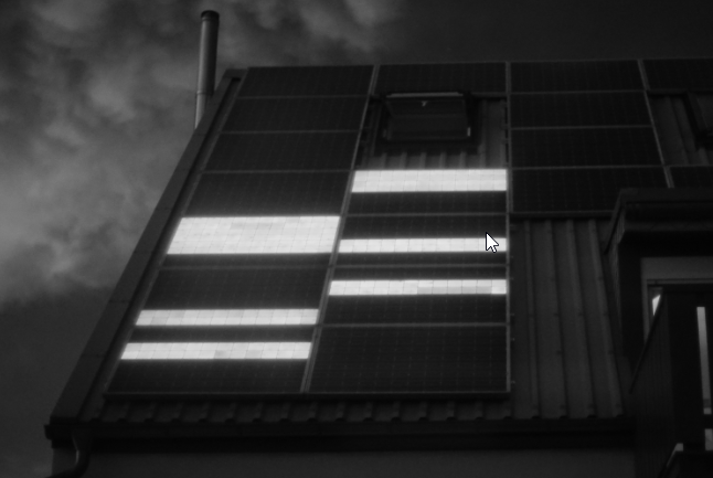
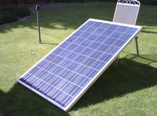
A small test in the garden behind our office ultimately made it possible to clarify what exactly goes on. For this, a bypass diode in a single solar module was short-circuited. After that, the module was shaded so as to approximately achieve an edge corresponding to the soiled one illustrated above.
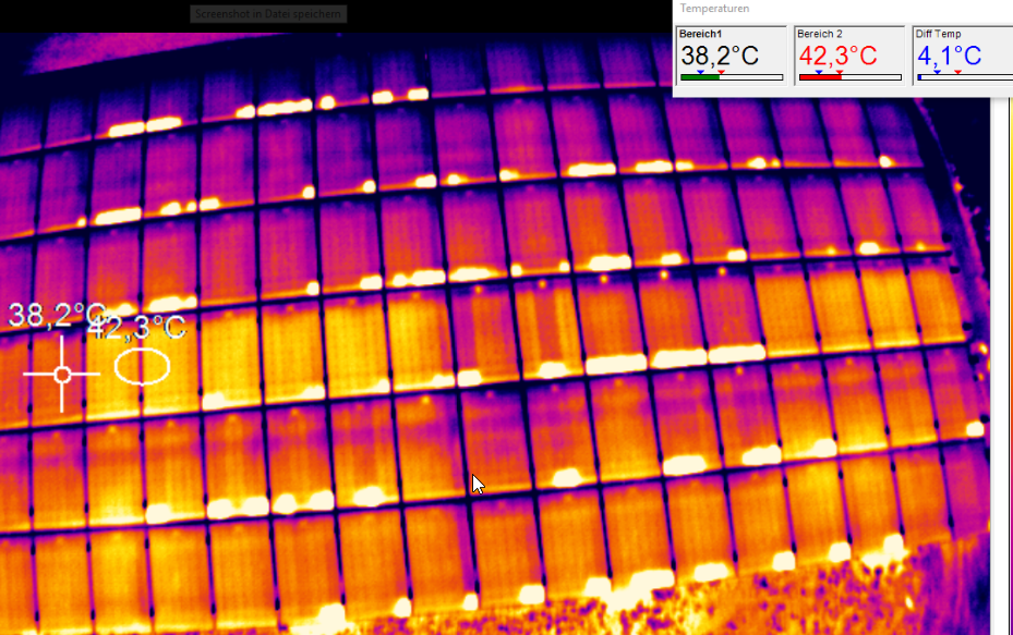
Shown next is the corresponding thermogram which shows the same effect as that seen on the drone thermogram.
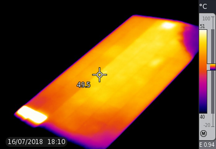
The substring with the shorted diode is slightly cooler than the neighbouring substrings to the right which are idle. The power obtained from the colder cells on the left is converted into heat by the heavily soiled or shaded cells, thus making them significantly warmer than all other cells in the module. Soiling or shading plays no role where substrings are in idle. The “hot cells” thus serve to clearly identify the defective bypass diodes.