In the previous post on checking bypass diodes in solar panels, I described in detail which faults could occur at the bypass diodes and how to detect missing diodes. Another problem that could arise, especially after instances of overvoltage, is a short circuit via the bypass diodes. This post focuses on this fault and the methods for detecting such faults. Like the previous post, this one isn’t particularly suitable for anyone who’s not interested in technology.
In accordance with VDE 0126-23, regular inspections of photovoltaic arrays should include measurements of the solar generators’ open-circuit voltage. Here, make sure that voltage levels for the individual strings are compared. Defective bypass diodes that short-circuit part of the affected panel are one fault that can be detected if these voltage measurements are carefully conducted. Unfortunately, a solar panel’s open-circuit voltage depends on a couple different factors: the temperature of the panel and insolation levels. In addition, two solar panels rarely have the exact same open-circuit voltage; production tolerances lead to slight differences in levels between strings. Before you conduct a measurement, consider which fault you’re actually looking for. You’ll need to know how many panels are in each string and how many bypass diodes are in each panel – usually three for crystalline panels. Then, divide the open-circuit voltage for the string with the highest level by the number of bypass diodes. The resulting voltage is the maximum allowable difference in voltage between two strings with the same number of panels. If the voltage difference between two strings is higher, a fault can’t be ruled out.

If you’re comparing voltage for two strings with different numbers of panels, then you’ll naturally need to convert your figures first. The utmost care is recommended when taking these measurements and analyzing the results, since a defective bypass diode isn’t the only issue that can impact open-circuit voltage; temperature differences between the individual panel strings, fluctuating insolation levels during measurements, and partial shading of a panel string can all have similar effects.
If you determine that there’s a significant difference in voltage between two strings with the same number of panels, the next step is to find out whether one of the bypass diodes is actually defective and, if so, which panel is affected.
There are two options here:
- Thermography (preferably reverse current thermography)
- Outdoor electroluminescence
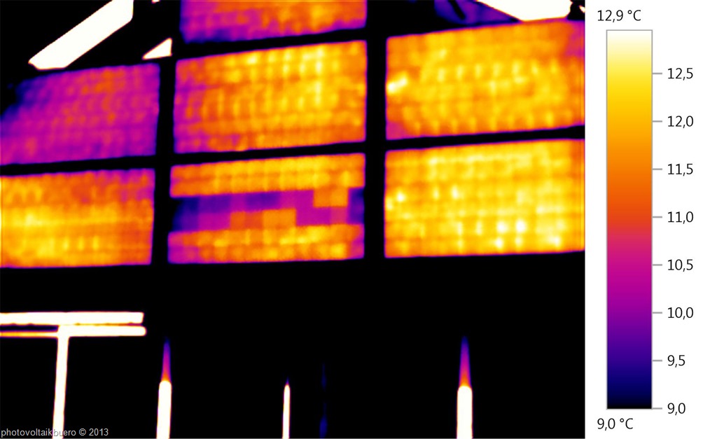
When conducting thermography during the day, you need at least 400 W/m² of irradiance in order to ensure that enough current is flowing through the panels. In the case of a panel with a short-circuited bypass diode, the short-circuit current from the best cells will flow in the affected part of the string (1/3 of the panel). Here, the “worse” cells consume electricity, resulting in the typical chessboard pattern of warmer and cooler cells in a thermographic image. This image is very different from the part of the panel with intact bypass diodes, where the cells have almost the same temperature.

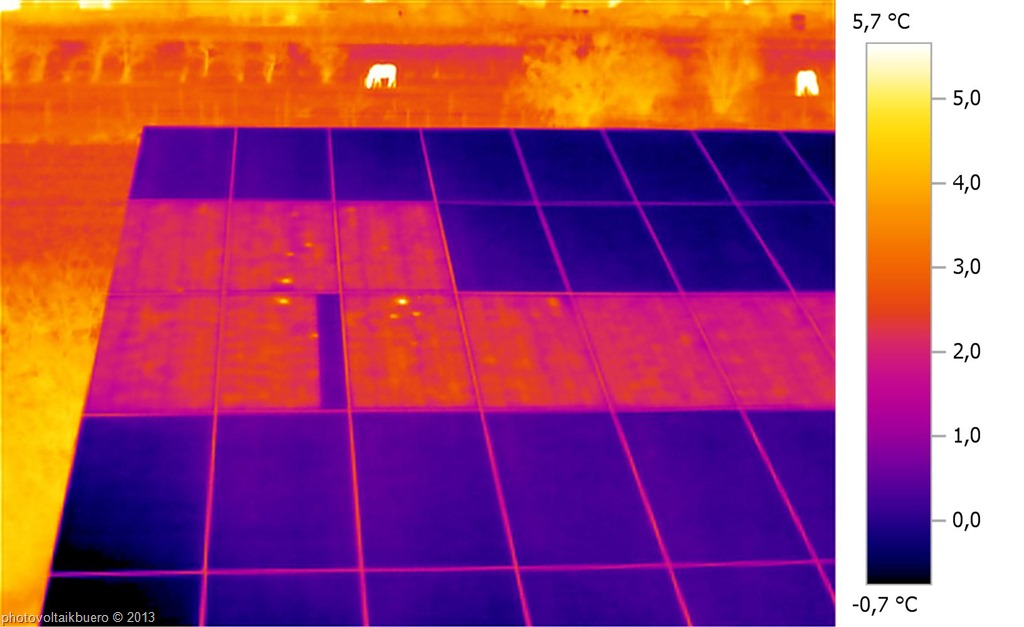
It’s even easier to track down short-circuited bypass diodes with reverse current thermography, in which a reverse current is sent through the panels. This method can be used in any weather conditions and at nighttime as well as during the day. The reverse current evenly warms up the solar cells it passes through, while the part of the panel with the defective, short-circuited bypass diode remains cool and is easily identified with the thermographic camera.

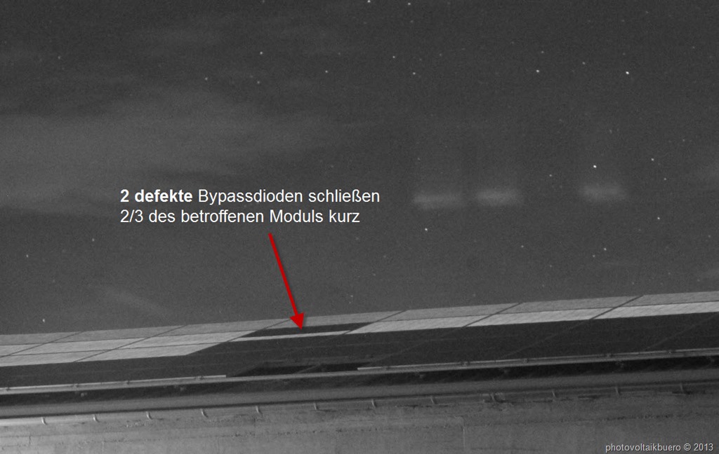
A reverse current is also sent through the panels in outdoor electroluminescence, but this method can only be used at night. The panels that the current passes through emit infrared radiation that can be recorded with a special camera. The defective bypass diode short-circuits part of the affected panel, which doesn’t emit any radiation and can thus be easily identified.


Thank you for your ever great articles.
I have a question on activated normal well functioning (i.e. not short circuited and not open circuited) bypass diodes:
If a by-pass diodes activates due to shading (lets say a large bird dropping), how will the thermal image of the module look like when the module is operating in the sun as part of a string: checker board or uni-formally heated up?
If a by-pass diodes activates due to a bad cell (lets say a severe crack), how will the thermal image of the module look like when the module is operating in the sun as part of a string: checker board or uni-formally heated up?
My guess would be checkerboard for both but I am not 100% sure.
When a bypass diode becomes active the voltage between anode and kathode is about 0,5V. When it’s shorted the difference between anode and kathode is 0V. That makes not much difference.
So in both cases checker board is right. But in the case of partial shading the shaded cell is the hottest one. I explain the situation in detail in this video: https://photovoltaikbuero.de/pv-know-how-blog/photovoltaik-blitzschutz-blitzfangstangen/ unfortunately it’s currently only available in german. I’ll check if I can find somebody to translate it …
But please keep in mind: Whether the bypassdiode is active depends also on the mpp-tracking of the inverter and whether the inverter is able to distinguish between absolute and relative mpps. I mention that, because not all inverters are able to do this. Some stick on an relative mpp (high voltage, low current) and the bypassdiode will not be active. In this case you’ll see no checker board.
Greetings to South Africa
Matthias Diehl
Thank you Matthias.