I have already described a number of methods here in the blog that you can use to discover and pinpoint almost any fault that can occur in a photovoltaic system – or so I thought. But then I came across a “tough cookie”, where it took several attempts to locate the cause of the reduced performance. That’s a good enough reason to write a blog article, I thought to myself. As the title suggests, it will appeal more to the tech freaks among this blog’s readers.
This is what happened. In a system with a total of 3 inverters, each of which is connected to a single string, one inverter occasionally experienced a significant loss of power compared to the other two. The system’s observant operator explained that the problem occurred more often on sunny days when one inverter would only supply about 500W, while the others were producing 3 kW from the same configuration.
As our experience over the past few years has been that carrying out an electroluminescence analysis (most articles only in german, sorry …) at night is the most effective way of getting to the bottom of most PV system problems, we began by carrying out our standard PV check (not translated yet). Unexpectedly, an analysis of the modules did not reveal anything unusual.
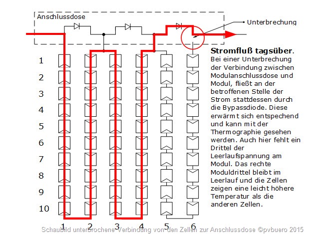
We did not find any defective bypass diodes, PID or high-resistance cell connectors. We then eliminated the possibility of open circuits between junction box and module, because we would otherwise have been unable to feed any reverse current into the modules. I described this fault, which reduces the open-circuit voltage of the affected string during the day, here.
After this initial analysis, we were only actually left with two options: it was either the inverter, which may have had a temperature problem, or the solar array, although the fault was only noticeable at higher temperatures. Since temperatures at night are normally a little bit lower, our first check revealed nothing. I then advised the customer to swap the module strings at the inverters, in other words, to connect module string of inverter 1 to inverter 2 and vice versa. This would tell us beyond any doubt whether the cause of the problem was on the roof or in the inverter. The result told us that the inverter was not the cause, as the problem now migrated from the first to the second inverter. It had to be caused either by the modules or by the DC line from the roof to the inverter.
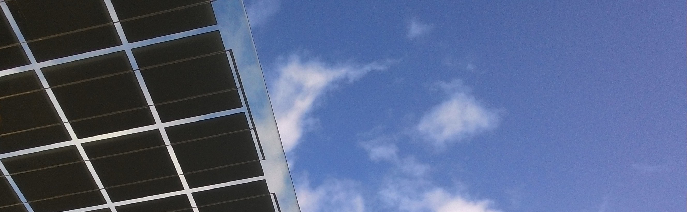
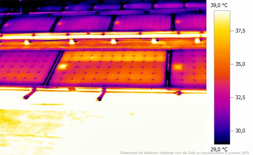
I then decided to make an appointment for a second site visit, this time during the day, armed with a IV curve tracer, a thermal imaging camera and the pvServe. We chose a hot summer’s day when we could expect the problem to start manifesting itself from around 11am. I had initially suspected that we might be dealing with a temperature-dependent open circuit between the module socket and the cells. This would be clearly visible in the thermogram (or at least I thought so).
Just to jog your memory: if a connection is open, there is no load on the corresponding part of the module and it is bridged by the bypass diode. This has two effects: first, the bypass diode of the affected module heats up a little, and second, the part of the module that is at no-load also becomes slightly warmer (approx. 2-4K) than the part running in MPP (Maximum Power Point) see here. The fault should have shown up clearly on the thermal image. That was not the case, however.
The head-scratching continued until I finally realised that both inverters – the one with the healthy module string and the one with the faulty string – were controlling the same DC voltage. These were transformerless inverters in which no DC/DC converter is used at the input, and both were operating at bottom of their voltage range (Umppmin) of approx. 350V.
The next step was to measure the IV curves of both module strings. This revealed that the problem string had a significantly lower open circuit voltage than the healthy string. The trend of the IV curves also revealed an abnormality in the open-circuit voltage.
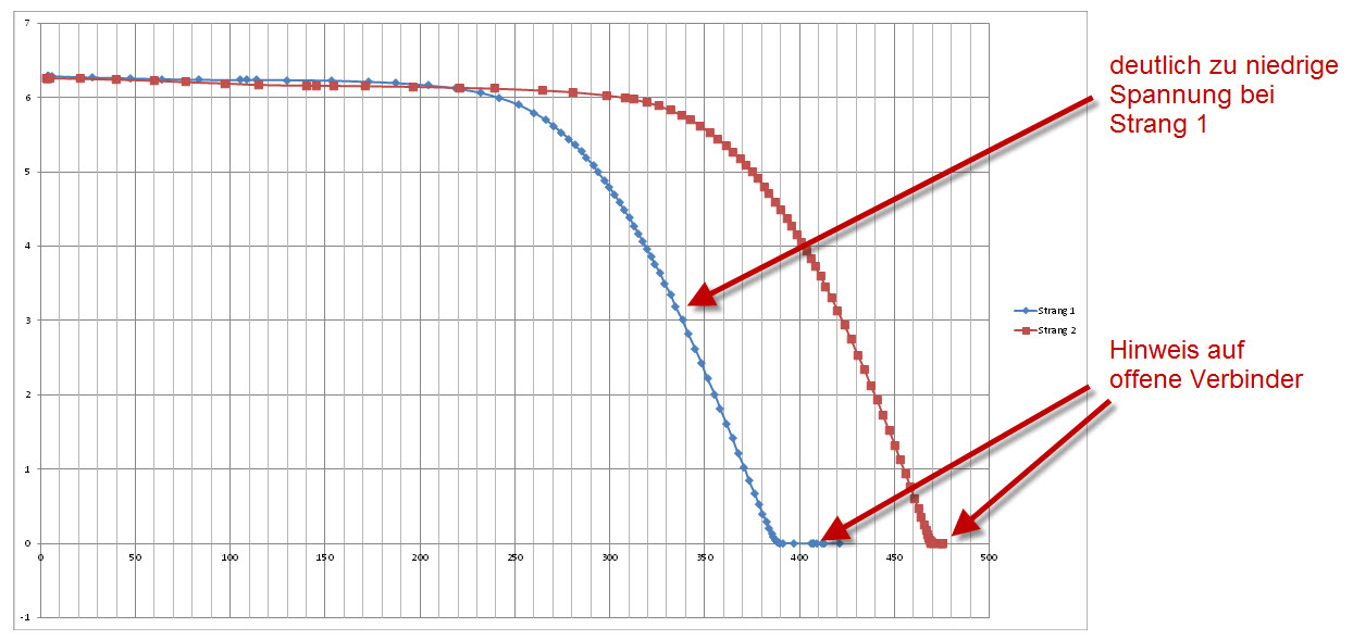
It was clear, therefore, that the problem string had to have a much lower MPP voltage than the healthy one. It was definitely not possible for both inverters to have set the same voltage of 350V. In other words, the faulty string was no longer being operated by the inverter in MPP because it was already working at the very bottom of its range. The string was almost at no-load (0.5A instead of 5.5A). This finally explained why nothing showed up on the thermal image. The temperature difference between cells that are at no-load and cells that are delivering a 0.5A current is so small that a thermal imaging camera has a real problem picking it up. It was therefore obvious that there were several breaks between the module junction boxes and the cells or between the cells.
The final proof came when we tried to feed a reverse current into the faulty string with the pvServe. It had worked flawlessly at night, but during the day, it was no longer possible. Even with a voltage of 1,000V, there was no flow of current whatsoever. That meant that there was definitely at least one discontinuity and that the bypass diodes had been able to block the 1000V without becoming damaged.
So we now knew the cause of the problem. It was definitely breaks between cells or between the junctionbox and the cells. All that remained to do was to locate the problem module. Unfortunately, because the inverter was already operating at its lower voltage limit (as explained earlier), the string with the faulty modules could not be made to return to the MPP.
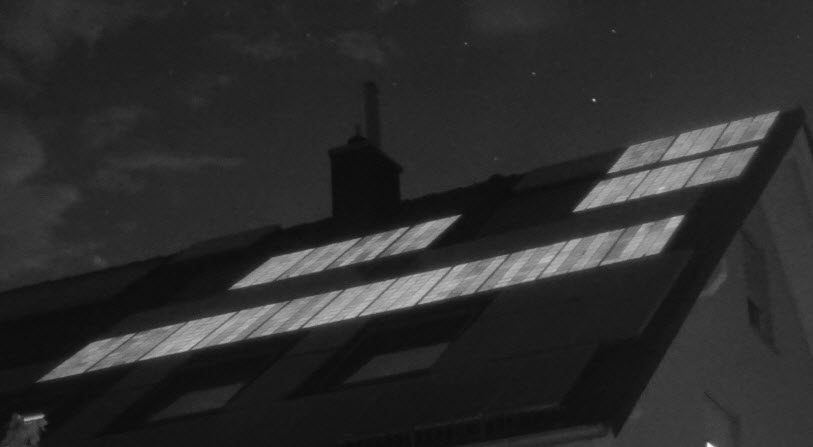
I then tried out a new method that I not yet used, and fortunately, that had the desired result. To understand this method, you need to be aware that short-circuited solar modules typically appear as a “chessboard” pattern in a thermal image, since some cells are significantly warmer than others. I have described in detail why this is so in this pvKnowHow blog article.(not translated yet) If you quickly short-circuit the entire module string, you will see this chessboard pattern wherever there is current flowing. No current can flow in places where the connectors between the junction box and the cells are open circuit; so the typical pattern does not appear. Instead, the cells have an even temperature. You can locate the defective modules by short-circuiting the entire string. Those modules or module sections that exhibit a uniform cell temperature in the thermal image have an interruption somewhere and must be repaired. The modules or parts of modules that display the typical chessboard pattern are fine.
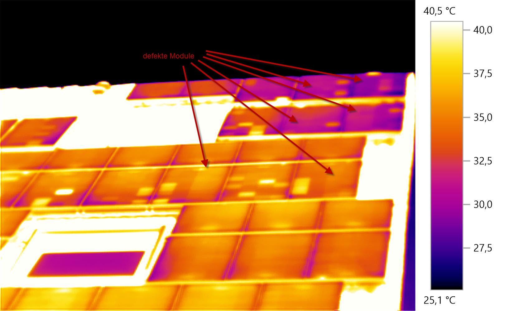
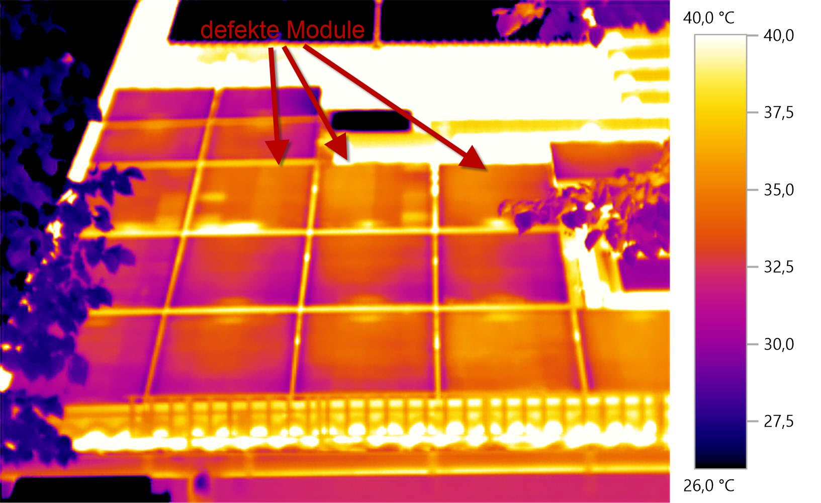
No sooner said than done. As the thermograms show, the method was very effective in locating the defective modules.
In closing, it is worth mentioning that short-circuiting the solar array string at full irradiation should only be done with a DC switch capable of handling the full load switching capacity. In other words, the switch must be able to disconnect the full short-circuit current of the modules and then be able to handle the full open-circuit voltage of the string in question. If the switch is not capable of doing this, there is a risk of electrical arcing with the potential of starting a fire. You should therefore know what you are doing and use a properly rated switch when attempting to copy the method explained above.
These case confirms that there is no “one” sure method when it comes to effectively analysing and finding faults in solar systems. In fact, a combination of different methods, together with a dash of detective work, is much more likely to lead to a successful outcome. If you would like to experience a structured presentation of the different methods, you are most welcome to attend one of our “Troubleshooting Seminars”.


Hi Matthias, I hope you are fine.
I want to short circuit an array but I can’t figure out what a DC breaker I should use, even reading the american NEC (we don’t have standards for PV in Uruguay)
For example the array has a Voc (-10ºC) of 505 V and a Isc of 9,45 A. Should I use a breaker with a rated voltage of at least 600 VDC for each pole or could a 2 pole breaker rated for 600 V do the job (even if each pole handles 300 V).
I’ve been looking on every webpage but I can’t get a definite answer on the subject.
Thanks.
Take a look at Santon (from the Netherlands). They produce DC switches for PV. Here you should find what you need.
Use a rated voltage of 600V for both poles because you can not be 100% sure that both switches switch off at absolutely the same time.
Matthias Diehl
Thanks Matthias!
As always you are of great help.
Thanks.
Hi Matthais,
This is an interesting read. Could hot cells cause junction boxes (by-pass diodes) to heat up and melt? I’ve experienced some burnt junction boxes (by-pass diodes) on some modules and on thermal imaging of the modules while short circuited, some cells have temperatures of 360K while adjacent cells are at 315K. (45K temp difference.) I notice from your images it seems you have hot cells too on at least 10 modules. Were you able to have a close up image of the affected modules? What was the condition of the by-pass diodes?
Regards,
Kimani Gichuche